
Laser & Photonics Components
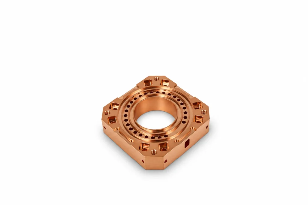
Custom A-QCW Annular Laser Diode Stack Package Housing
Precision-machined annular housing for A-QCW laser diode bar stacks used for side-pumping rod-shaped gain media. Housing only, to customer drawings.
ExploreTry a part name, a material (Kovar, SUS304) or a process (CNC turning, anodizing). Press Enter for full results.
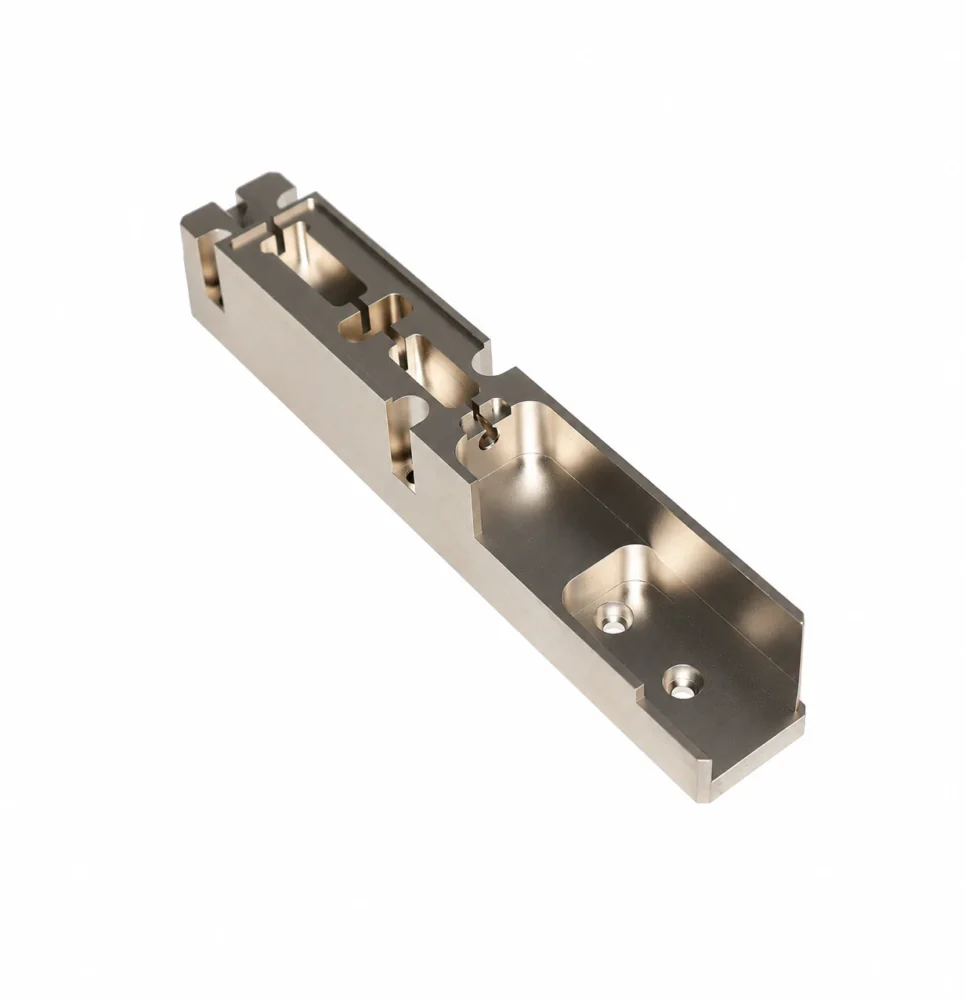
Custom precision-machined fiber optic mounts and holders designed for positioning, supporting, and securing optical fibers or related optical components.
Design considerations
Technical specifications
| Parameter | Value | Unit / Note |
|---|---|---|
| Product type | Custom Fiber Optic Holder | |
| Material options | Stainless steel / aluminum / copper alloys and specified machinable metals | Design review; not interchangeable by default |
| Critical features | Fiber positioning slots, mounting holes and alignment surfaces | |
| Finish | Gold / nickel / selective plating; thickness and coverage per drawing | |
| Dimensions and tolerances | Per approved drawing | Reviewed for material, geometry and process |
| Inspection | Dimensions and visual condition; CMM for applicable features | Methods and reports agreed per project |
Values shown are per this product entry; customer drawings take precedence.
Manufacturing
Applications
Optical communication modules and subassemblies; fiber alignment and mounting structures; laser and photonics equipment; optical sensing and test instruments; custom optomechanical fixtures. Specific end use depends on the customer design.
Provide the drawing revision, 2D drawing and STEP model, quantity, material grade, requirements for fiber positioning slots, mounting holes and alignment surfaces, coating areas and thickness, and acceptance criteria. Photographs show custom variants, not a standard size or pin count.
Insulation, leak tightness, vacuum suitability, electrical ratings and thermal performance require design-specific verification under agreed conditions; appearance or material alone does not establish them.
FAQ
Provide the drawing revision, 2D drawing and STEP model, quantity, material grade, requirements for fiber positioning slots, mounting holes and alignment surfaces, coating areas and thickness, and acceptance criteria. Photographs show custom variants, not a standard size or pin count.
Fiber positioning slots, mounting holes and alignment surfaces; dimensions, tolerances and process compatibility are confirmed during engineering review.
No. Tolerances depend on the drawing, material and geometry. Insulation, leak tightness, vacuum suitability, electrical ratings and thermal performance require design-specific verification under agreed conditions; appearance or material alone does not establish them.
More in this family
Laser & Photonics Components
Precision-machined annular housing for A-QCW laser diode bar stacks used for side-pumping rod-shaped gain media. Housing only, to customer drawings.
ExploreLaser & Photonics Components
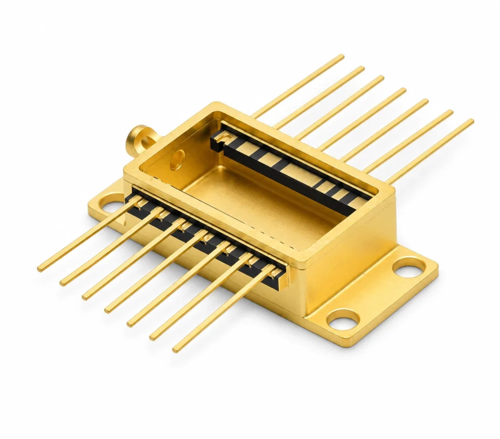
Jingyixin manufactures custom high-precision ceramic-to-metal package housings for electronic, optoelectronic and sensor assemblies.
ExploreLaser & Photonics Components
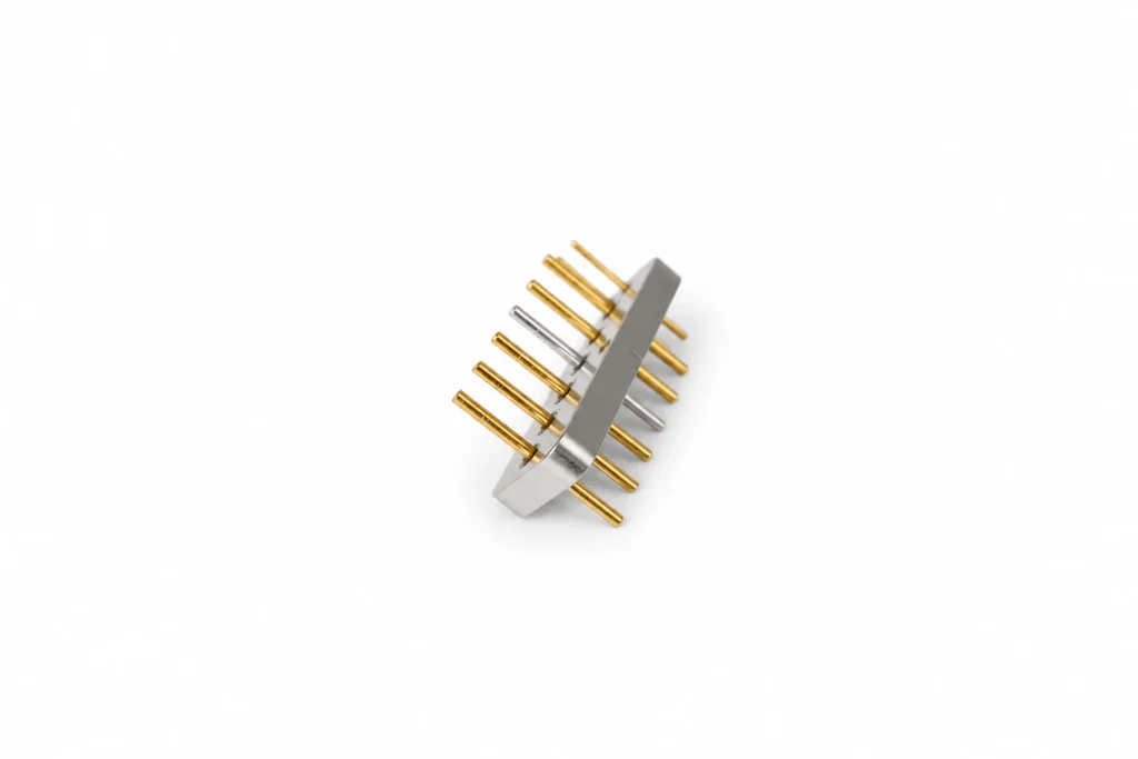
Jingyixin manufactures custom high-precision dual-row multi-pin electrical feedthrough assemblies for electrical interconnection in optoelectronic packages, laser systems, semiconductor equipment and industrial instruments.
ExploreRequest a Quote
Share your drawing, material, quantity and critical requirements for a manufacturing review.