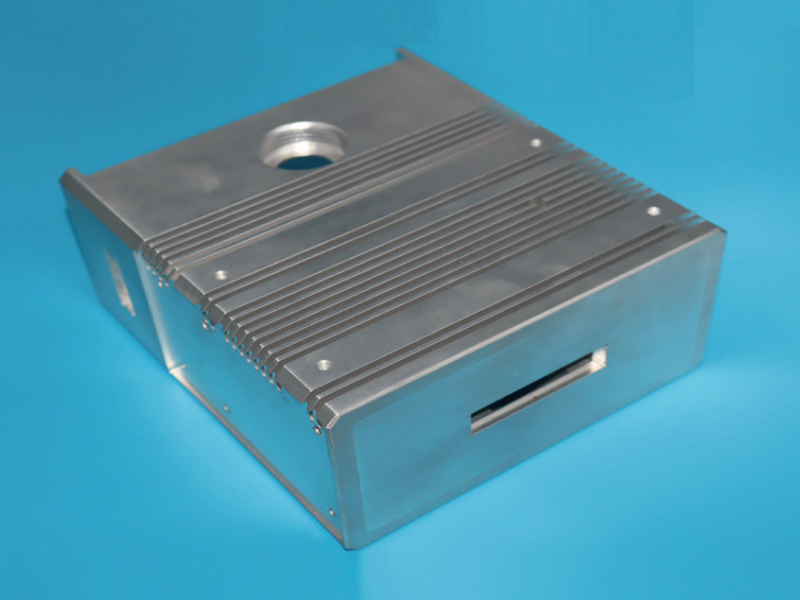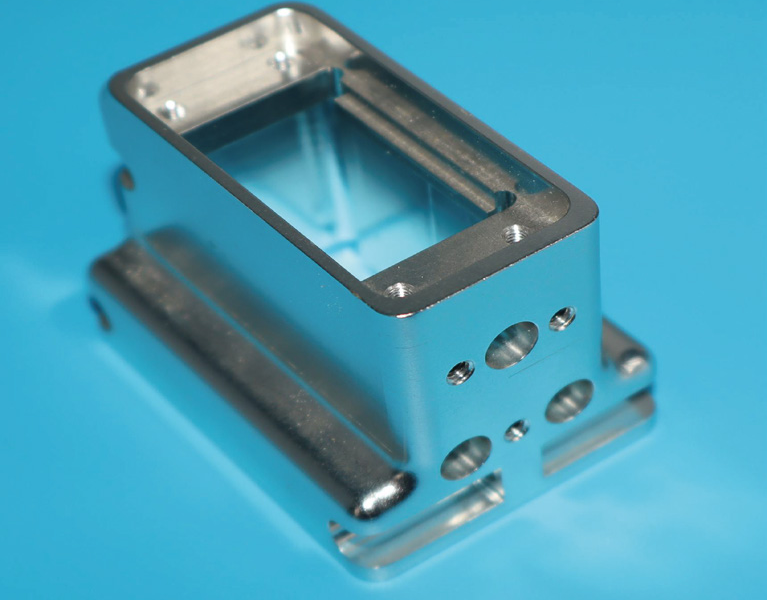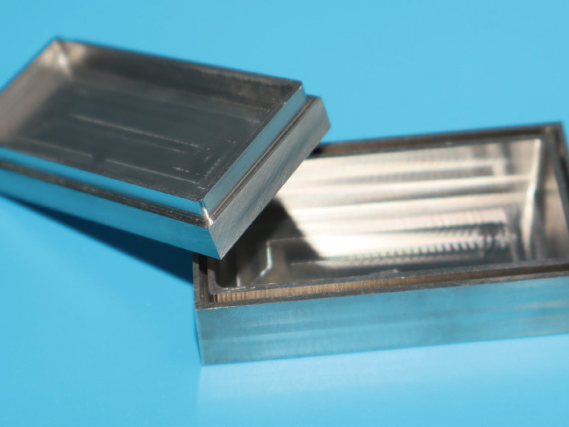

In one paragraph: ±0.005 mm on a critical feature is routine for a shop that manages it deliberately — thermally stable machines, sharp tooling, rigid workholding and CMM verification — but it is a per-feature decision, not a drawing-wide default. Applied only to the dimensions that carry function (sealing faces, bores, mating locations), it costs little; applied to every dimension, it multiplies machining and inspection cost for zero benefit.
What the number actually means
General-purpose machining is typically quoted at ±0.02–0.05 mm. A ±0.005 mm callout is ten times tighter, and every element of the process chain — machine, tool, fixture, thermal state and measurement — must be controlled at the same time. Weak links compound: a warm spindle, a worn insert or a flexible fixture can each consume the entire budget on their own.
The four factors that decide whether you can hold it
1. Thermal stability
Steel grows about 11–12 µm per metre per °C. A part measured at 22 °C and machined at 26 °C is already out of budget on a 150 mm dimension. Production shops that hold ±0.005 mm run machines warmed to operating temperature, keep coolant temperature controlled, and measure in a room held near 20 °C.
2. Tool condition and compensation
Tool wear is not optional — it is a budget line. Diameter measurement between cuts, and wear compensation applied at roughing rather than finishing, keeps the last pass light, cool and predictable.
3. Rigidity of the whole system
The machine is only one element. Thin walls and tall stands amplify cutting force variation into dimensional error. Where a feature must hold ±0.005 mm, the fixturing plan matters as much as the machine: support close to the cut, clamp on rigid zones, and finish critical features in one setup so datum references never move between operations.
4. Verification you can trust
A tolerance that cannot be measured does not exist. At ±0.005 mm, calipers and micrometers are out of their depth — calibrated CMM measurement with a documented gauge study is the practical floor. Ask a supplier how they verify the number, not only whether they can quote it.
Where to apply it — and where not to
| Apply tight tolerances to | Leave at general tolerance |
|---|---|
| Sealing and O-ring groove dimensions | Cosmetic surfaces |
| Bore and shaft fits for bearings | Non-mating pocket floors |
| Datum faces and alignment features | Housings with generous clearances |
| Optical/fiber alignment holes | Vent slots, cable passages |
The pattern: tighten what carries function, leave air elsewhere. A drawing with three tight features and twenty loose ones is both cheaper and more reliable than the reverse.
The honest cost curve
Tightening a feature from ±0.01 mm to ±0.005 mm typically adds a separate finishing pass, slower feeds, more frequent measurement and often 100% inspection of that feature — not a linear price increase, but a step. On the few features that need it, the step is worth paying. This is exactly the trade-off a DFM review should surface before quoting, feature by feature.
How we approach it
Our published capability benchmarks state what each process holds under controlled conditions, and every RFQ gets an engineering review that flags which of your callouts are comfortable, which are at the limit, and which cost more than their function justifies. Have a drawing with a few critical dimensions? Send it in — you will get a specific answer, not a generic yes.