
On this page
Engineering summary. A brazed or welded joint that looks good is not a joint that is good. The failure you care about — a coolant leak at a sealed housing — starts as a void, an incomplete fillet or a bridged channel that no eye can see from outside. So “we inspected it” means nothing until you say which test, at what rate, on what sample. This page is about verifying a joint: what each test actually finds, what it misses, and how to write an acceptance criterion that a shop can meet and you can check.
Visual inspection catches the obvious and nothing else
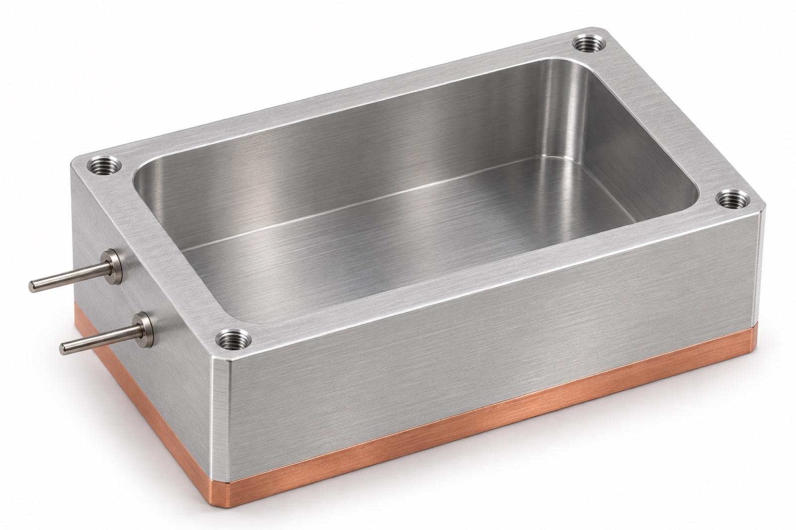
Start with the eye, but do not stop there. A visual check under good light finds an external fillet that did not form, a gap at the edge, oxidation scale or a burnt area — the signs of wrong heat or poor flux. What it cannot see is the inside of the joint: a channel bridged by filler metal, a void under a fillet that looks continuous, or a crack that has not opened yet. On a flat sealing face a visual pass is necessary and never sufficient. Write down the illumination and the sampling plan, or two inspectors will pass two different parts.
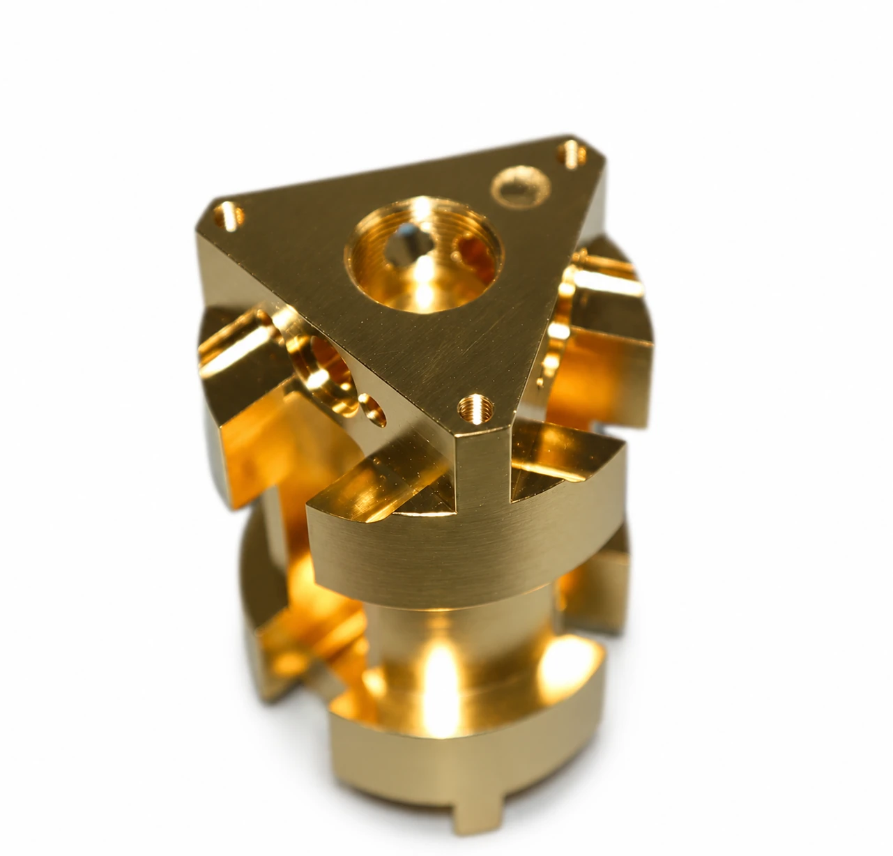
The non-destructive tests do different jobs — match the test to the defect
- Liquid penetrant (PT): a dye drawn out of a surface-breaking crack or porosity. Good for surface defects on an accessible face; blind to anything below the skin or on an internal channel.
- Radiography (X-ray, RT): shows voids, inclusions and gross gaps through the thickness. Good for internal volume defects; it is much weaker on tight planar cracks that lie parallel to the beam, and it needs access from both sides.
- Ultrasonic (UT / C-scan): maps voids and unbonded areas across a bonded plane, and is the workhorse for plate-type joints where the bond is a large area. It needs a known reference and a skilled operator; a C-scan is only as good as its calibration.
- Helium mass-spectrometry leak test: measures tracer-gas leakage under the agreed pressure, temperature and test setup. Compare the reading with the specified threshold. The reading alone does not quantify coolant leakage in service.
The mistake is to pick one and call it “inspected.” PT finds a surface crack the leak test would never see; the leak test finds a through-path PT would miss. On a critical joint you specify more than one, each aimed at a different defect.
Pressure and burst: proof of strength, not of leak-tightness
A hydraulic pressure-hold proves the joint carries static pressure for the hold time without rupture. A burst test proves the margin to failure on a sample. Neither proves absence of a micro-leak — a joint can hold pressure and still weep at a rate below what the gauge sees. That is why pressure testing and tracer-gas leak testing are separate requirements, not alternatives: proof pressure for structural integrity, helium for leak-tightness, and often a thermal cycle in between to open a marginal joint before the final leak check.
Destructive tests prove the process, not the part
Cross-sectioning and shear/burst testing destroy the sample, so they are run on a coupon or a sacrificial part from the same batch and process. What they give you is the truth about the joint you cannot see: a section under a microscope shows whether the filler filled the gap, whether there are voids, and — under SEM/EDS — whether the braze zone is a continuous sound structure or a brittle intermetallic layer. This is the difference between “the process is capable” (coupon passes) and “this specific part is good” (which only the non-destructive tests on that part can say). Use destructive tests to qualify the process and set the window; use NDT and leak test to accept the parts.
| Method | What it checks | Acceptance inputs |
|---|---|---|
| Visual / penetrant | Visible or surface-breaking indications | Define accessible surfaces, lighting or indication limits |
| Radiography / ultrasound | Internal indications in suitable geometry | Define coverage, method, reference and limits |
| Proof pressure | Structural behavior during a defined pressure hold | Record medium, pressure, duration and pass criteria |
| Tracer-gas leak test | Through-leakage under the defined setup | Record tracer, pressure differential, temperature and leak-rate limit |
For single-phase direct-to-chip cold plates, see the separate leakage and pressure methods in OCP Cold Plate Test Specification 1.0.0, §5.1.
Writing an acceptance criterion a shop can meet
“Leak tested” and “visually inspected” are labels. A usable specification names four things for each test: the method (helium mass spectrometry, PT, UT C-scan, proof pressure), the acceptance threshold (a leak rate in mbar·L/s, a max void area, a proof pressure and hold time), the sample (100% or a defined sample size and plan), and the report (what the supplier must send with the part). Without the threshold, “passed” is the supplier’s opinion. With it, you can compare two quotes and reject a bad lot on the data.
What we make, and what we do not
JYX reviews joining requirements against the drawing, including low-temperature copper-to-aluminum joining. Provide the required tests and acceptance thresholds. Before quoting, confirm test feasibility, who will perform each test, samples, sampling and required reports.
We do not sell a joint as “hermetic” without a test and a rate to back it, and we do not claim a leak class beyond what is measured on your part. We will tell you when the test you asked for cannot detect the defect you actually fear — a leak test will not find a sub-surface void, and a visual check will not find a bridge inside a channel. Specifying the wrong test is worse than none, because it gives false confidence.
What to send with the RFQ
Send the drawing revision, 2D drawing and STEP model; the materials to be joined and the joint design; the service condition (coolant, pressure, temperature range, cycles); the defect you are most concerned about (external crack, internal void, through-leak); the test you want and its acceptance threshold (leak rate, void limit, proof pressure); the sample plan (100% or lot-sampled); whether a thermal cycle is required before final leak test; and the report and traceability you need. With those we can specify a test that finds the failure you care about, not just one that stamps the part.
Copper-aluminum brazed housing · Send your drawing and acceptance requirements
Frequently asked questions
Is a pressure-hold test enough to prove the joint will not leak? No. It proves the joint holds static pressure for the hold time. It does not prove absence of a micro-leak a tracer-gas test would find. For a sealed housing, specify a helium leak test with a rate, and consider a thermal cycle before it.
Why not just look at it and leak test it? Because the two find different failures. Visual catches a missing external fillet or a surface crack; the leak test catches a through-path neither the eye nor a surface test sees. Neither catches a sub-surface void that has not yet opened — for that you need UT or a destructive coupon.
What leak rate should I specify? One that matches the consequence of a leak in service, not a round number. A coolant housing next to electronics is different from a low-pressure manifold. State the rate in mbar·L/s, the method (helium mass spectrometry), and 100% or sampled, and the shop can meet a number instead of guessing.