
On this page
Engineering summary. A machined bracket is not a small housing. A bracket is an open, often thin, three-dimensional part whose job is to hold something else in position — so its failures are not leaks or voids, they are movement: a wall that deflects under load, a face that warps a day after machining, a hole pattern that is right on the bench and wrong once bolted. This page is about designing and quoting a CNC-milled bracket so it holds position, not just so it looks finished.
The hard part of a bracket is stiffness, not shape
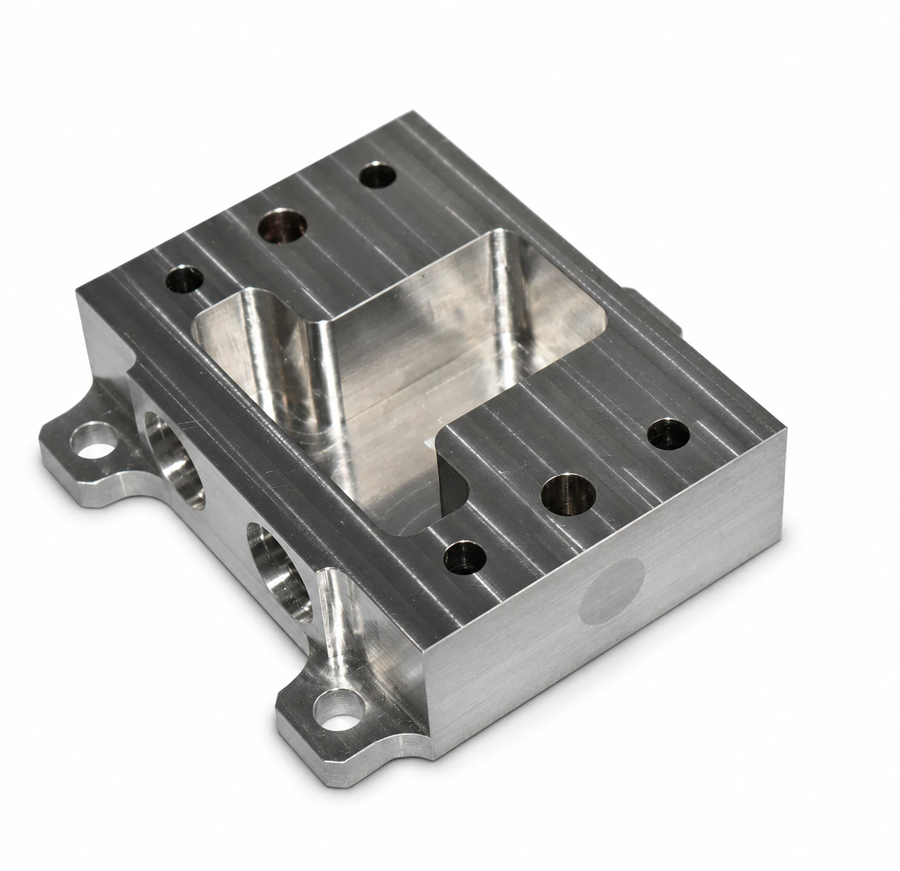
Housings are closed and rigid; brackets are open and, to save weight, often thin. That changes what fails. A bracket fails by moving: a wall flexes under the load it carries, a long ear vibrates, a pocket floor deflects. The number that predicts trouble is not wall thickness alone but the aspect ratio — wall height divided by wall thickness. A tall thin wall at a high aspect ratio deflects and then springs back, which leaves chatter marks and takes the finished dimension off; a short thick wall at the same thickness is fine. So when you design a bracket, the question is not “how thin can I make it” but “does this wall have enough support, or a rib, for the height it has.”
Clamping and residual stress: the part that warps after it leaves the machine
Two distortions hit brackets and both are invisible on the drawing. The first is clamping: a thin wall held too hard is pressed out of shape while it is cut, then springs back when released, so the machined face is no longer where the tool left it. Thin brackets need soft jaws or a dedicated fixture, and the clamping force has to be enough to hold the part and not so much that it deforms it. The second is residual stress: removing material from plate or bar releases stress that was locked in, and the part can move — not during the cut, but hours or days later. A bracket that measured flat at inspection can bow in the field. For a flat or critical face, ask for a stress-relief step and for flatness measured after the part has settled, not straight off the machine.
Flatness and hole position are two different requirements
On a bracket, the mounting face and the hole pattern do different jobs and fail for different reasons. The face fails by warping or by an uneven clamp; the holes fail by tool wear, taper or runout, or by being placed relative to the wrong datum. Two holes can each be the right diameter and still not bolt up, because their positions relative to the datum are off. That is why a position tolerance (GD&T position) is a better control on a hole pattern than a stack of tight ± coordinates — it says what actually matters: where the hole is, relative to the datum, within a zone. Put the datum scheme on the drawing and let the position callout do the work.
| Feature | Drawing input | Verification |
|---|---|---|
| Datums | Identify the mating references and datum order | Establish the specified datum reference frame |
| Mounted flatness | Identify the surface and clamping or fastening conditions | Measure in the specified condition |
| Hole position | Give the position tolerance and datum references | Check hole axes against the drawing datums |
Tolerance is per-feature, not one number for the part
Assign tolerances by function. Identify the assembly datums, critical surfaces and hole pattern, and state the inspection condition. ±0.005 mm is a capability benchmark for suitable geometry, support and inspection conditions. Confirm achievable tolerances feature by feature against the drawing.
Design choices that make a bracket easier to hold to spec
- Ribs and bosses instead of one thin wall. A rib lets you keep weight down without an unsupported tall wall that deflects.
- Generous internal radii, no sharp inside corners. A sharp corner in a pocket is where a small tool chatters and where stress concentrates.
- Faces you can actually clamp. A face the fixture can seat on machines flat; an awkward overhang does not.
- One clear datum scheme. Pick the mounting face and two holes as the datum and dimension everything from them, not from a chain of edges.
- Tell the shop which face is the control face. The one face and the one hole pattern that decide whether the part works should be the tightest thing on the drawing.
What we make, and what we do not
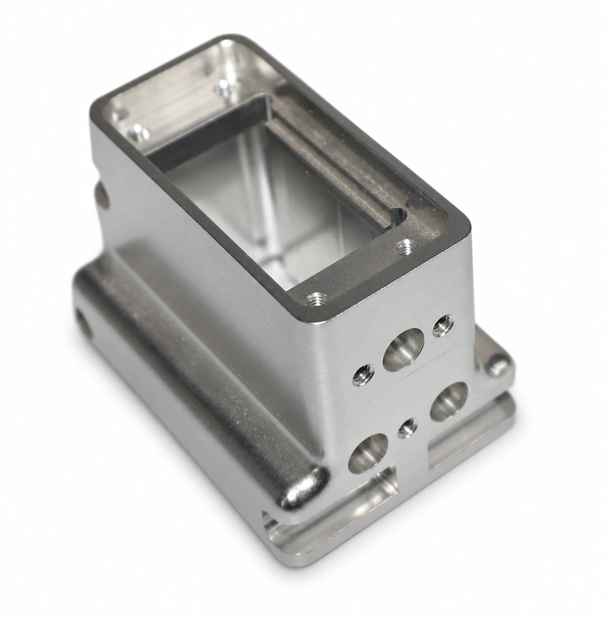
We CNC-mill structural parts — brackets, mounts, plates and multi-face frames — in aluminium, stainless and other machinable metals, to a drawing, with the critical faces and hole patterns inspected as specified. Our milling capability page cites a ±0.005 mm benchmark; that is a reference for what well-supported features can hold, not a promise that every feature on every bracket hits it.
We do not quote a single guaranteed tolerance for a whole part, because a thin wall and a solid boss are not the same machining problem. We will tell you which features on your bracket are at risk before we cut — a wall that is too tall for its thickness, a datum that is a chain of edges, a face the fixture cannot seat on. What we will not do is accept a drawing that cannot be held and stay quiet about it.
What to send with the RFQ
Send the drawing revision, 2D drawing and STEP model; the material and condition; the faces and hole patterns that are functional (so they can be the tight features and the datum); the flatness requirement and whether it must hold after settling; the loads the bracket carries and where it mounts; which surfaces are cosmetic versus functional; the surface finish or coating; and the inspection and acceptance criteria. With those we can tell you which features are hard, quote realistically, and flag the one design change that saves the part.
Custom CNC milled bracket · Send your drawing and acceptance requirements
Frequently asked questions
Why did my bracket warp after machining? Almost always residual stress released by removing material, sometimes combined with a clamp that was too hard. On a thin or critical face, a stress-relief step and flatness measured after the part settles — not straight off the machine — are what keep it flat.
My holes are the right size but the part will not bolt up. Why? The hole positions, not the diameters, are off — usually measured from the wrong datum or from a chain of edges. Dimension hole patterns with a position tolerance from a clear datum scheme.
Can you hold ±0.005 mm on my bracket? The answer requires drawing review. Identify the critical feature, datums and inspection condition, and include the mating geometry if available.