
On this page
Direct answer: a high-power laser diode converts only part of its electrical input into light — the rest becomes heat that must be removed fast to protect efficiency, wavelength and lifetime. A macro-channel water-cooled heat sink carries that heat away through a copper heat-spreading base and relatively large internal channels, trading some ultimate heat-transfer density for lower pressure drop, easier cleaning and robust sealing. This deep-dive explains why laser diodes need liquid cooling, how macro- and micro-channels differ, the architecture, the manufacturing challenges and how performance is verified.
Why high-power laser diodes need liquid cooling
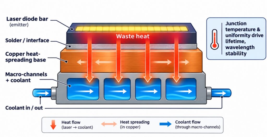
A laser diode’s wall-plug efficiency — the fraction of electrical power converted to optical output — is well below 100%, so a significant share of the input power becomes waste heat concentrated in a very small emitting area (a “bar” a few millimetres wide). As output power rises, natural convection and conventional finned heat sinks cannot remove that heat within the available footprint. Two temperatures matter most:
- Junction temperature — too high shortens lifetime and lowers efficiency (excess heat accelerates degradation of the active region and solder interfaces).
- Temperature uniformity across the bar — gradients cause different emitters to drift to different wavelengths and misalign, degrading beam quality and spectral stability.
Liquid cooling addresses both by moving heat out through conduction into a circulating coolant, holding junction temperature and module gradient under control. It matters on five fronts: heat removal, output stability, lifetime/reliability, lower flow resistance (with suitable geometry) and module integration for bars, arrays, stacks and pump modules.
Macro-channel vs micro-channel
Macro-channels are relatively larger; micro-channels are finer. There is no single fixed size boundary between them. The practical differences:
| Macro-channel | Micro-channel | |
|---|---|---|
| Channel size | Larger cross-section | Fine (sub-millimetre) |
| Heat transfer per volume | Good — balances cooling with flow | Higher potential, but stricter demands |
| Pressure drop | Generally lower for comparable flow | Higher (steep with narrowing) |
| Clogging sensitivity | Less sensitive to particles | Requires strict filtration & clean coolant |
| Manufacturing | CNC machining + joining/sealing | Finer channels + bonding control |
| Selection driver | Pressure budget, reliability, maintenance | Maximum flux in minimal volume |
Selection should be driven by heat flux, pressure-drop budget, pump capability, reliability and maintenance conditions — not channel size alone.
Typical architecture
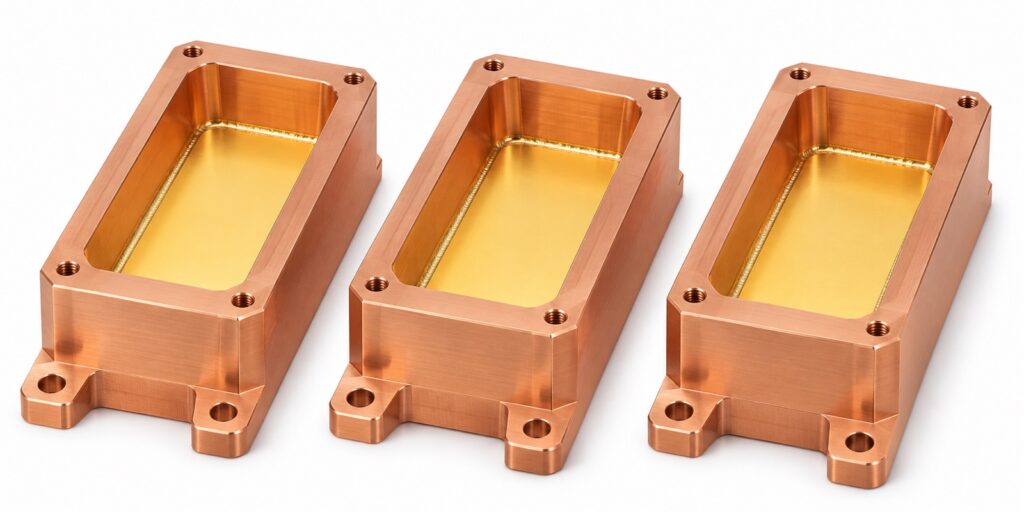
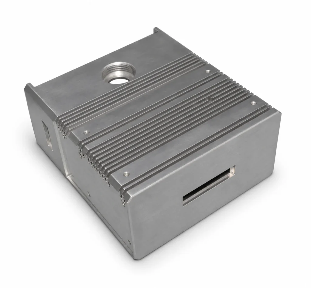
A macro-channel water-cooled heat sink usually combines: a heat-spreading base that carries the laser assembly and conducts heat to the channel walls (copper or copper alloys are common, subject to design); internal channels through which heat passes from the walls into the coolant; ports and manifolds that direct coolant inlet, distribution and outlet to avoid locally starved flow; a cover and seals that enclose the channels using a specified brazing, welding or other sealing method; and flanges, mounting holes and datums that secure the module and control assembly alignment. The heat path runs: laser chip → solder/interface layer → heat sink base → channel wall → coolant → external cooling system.
Challenge 1 — Channel machining
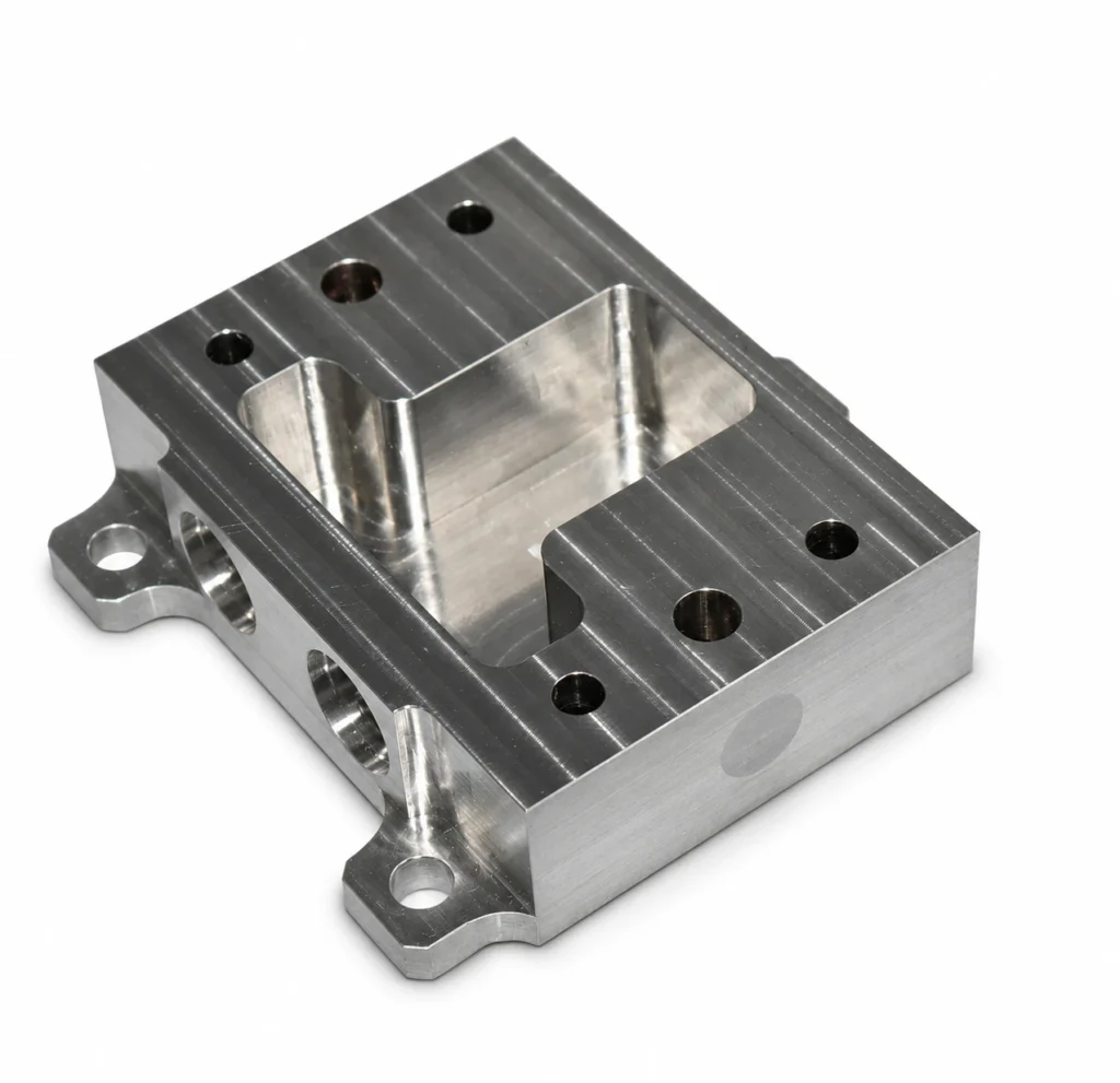
Manufacturers must control channel cross-section, position and burrs, and avoid sharp features, debris and partial obstruction that would disrupt flow distribution. Uniform manifold distribution matters as much as the channels themselves — a well-made channel set with a poor manifold still starves some emitters.
Challenge 2 — Precision copper machining
Copper conducts heat well but can cause built-up edges, burrs and local distortion during machining. Flatness of the mounting face, surface finish and critical fits all need control, because a poor mounting flatness or contact adds interface resistance that no amount of channel design can recover.
Challenge 3 — Brazing and sealing
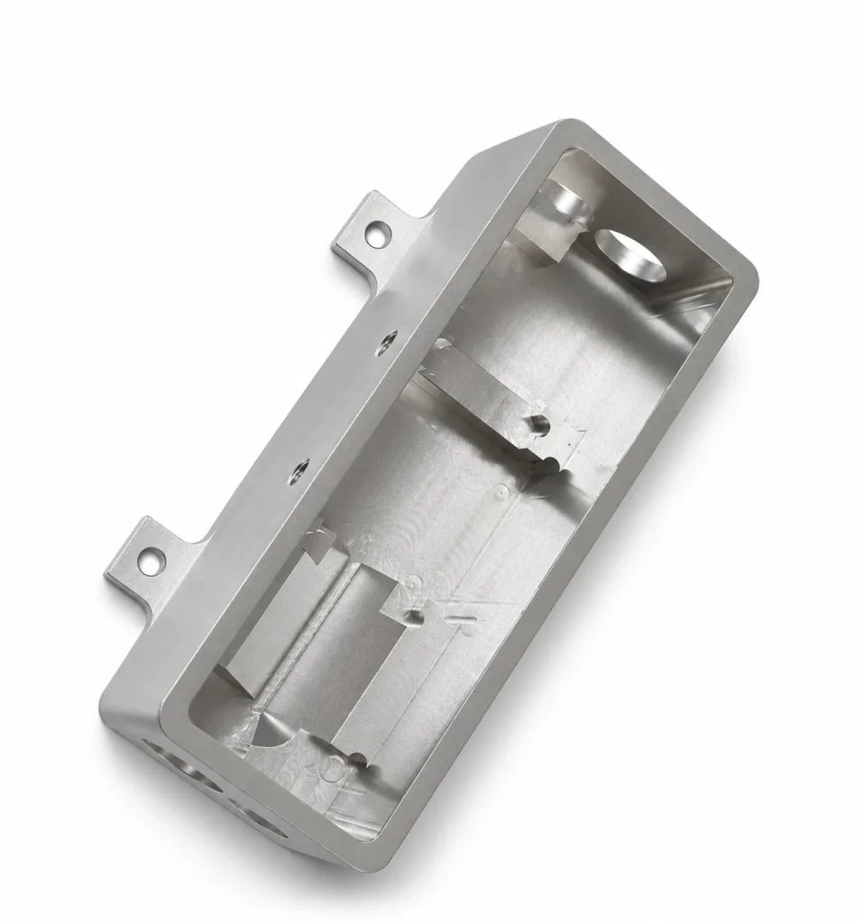
Multi-piece designs require control of braze flow, joint clearance, thermal distortion and leakage risk — particularly preventing filler metal from entering the channels. The thermal cycle must seal every edge without warping the mounting datum.
Challenge 4 — Inspection and validation
Beyond dimensional inspection, the finished part should go through leak, proof-pressure, flow and pressure-drop testing — and, where required, thermal-performance testing — to the customer’s specifications. A continuous-looking seam does not prove leak-tightness; only a defined test does.
What “cooling performance” actually depends on
System-level cooling is not set by channel size alone. The important levers are: the heat load to be removed, the allowable junction temperature, the coolant type and inlet temperature, the flow rate and resulting caloric rise, the pressure budget, the interface/contact quality between device and base, and the coolant cleanliness (which governs whether the channels stay open over time). A cold plate specified only by “channel size” without these inputs is under-specified.
Representative process route
Engineering review of 2D/3D drawings, materials, channel design, joining structure, coolant and acceptance criteria → CNC machining of external features, mounting details, channels and sealing interfaces → cleaning and deburring to minimise contamination and blockage → surface finishing and suitable brazing as specified → final dimensional plus sealing and hydraulic verification. The exact sequence depends on material and joining compatibility.
Applications
Typical uses include high-power laser diodes, QCW laser diode stacks, solid-state laser pump modules and industrial laser systems. Other high-heat-flux power electronics (IGBT modules, dense ASICs) use the same macro-channel logic.
Frequently asked questions
Why not just use a bigger metal heatsink?
Passive area becomes impractical at high heat flux and in tight footprints; liquid cooling moves far more heat per unit volume and holds junction temperature and gradient where air cannot.
Is macro-channel “worse” than micro-channel?
No — it trades peak heat-transfer density for lower pressure drop, easier cleaning and more robust sealing, which is often the right choice for laser modules that must run reliably for years.
Can you state a thermal resistance number?
Only together with the coolant, flow, heat load, interface and test setup. This article is a technical overview, not a measured performance claim for any pictured part.
Conclusion
The value of macro-channel cooling lies in balancing heat removal, hydraulic resistance and operational reliability. JYX CNC supports precision CNC machining, channel fabrication and project-specific joining, finishing and inspection. This article is a technical overview, not a claim that any pictured product has a verified internal layout or measured performance; tolerances, pressure ratings and thermal metrics require formal specification and validation.
Discuss a laser cooling project
Working on a high-power laser diode, laser stack or pump module that needs a water-cooled heat sink? Share your drawings, thermal and flow requirements, materials and acceptance criteria with JYX CNC for an engineering review.
Review the macro-channel water-cooled heat sink and joining capability against the project requirements. Request a drawing review for your laser cooling component.
Sources
- Tuckerman & Pease, microchannel heat-sink work, MIT Lincoln Laboratory (basis for liquid-cooled high-flux components). MIT LL
- Copper Development Association, thermal reference data. copper.org
- Reference melting point & hardness data for copper alloys used in laser heat sinks. reference table
Technical overview only. Tolerances, pressure ratings and thermal metrics require formal specification and validation.