
On this page
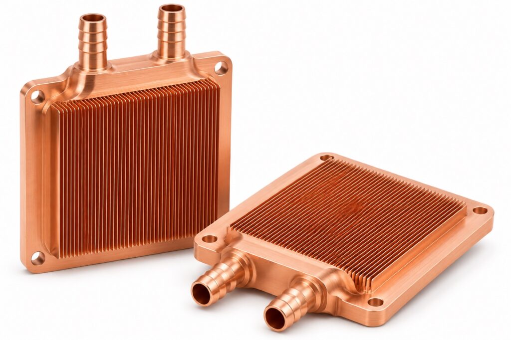
Direct answer: a copper microchannel heat sink removes very high heat flux from a small footprint by pushing coolant through many narrow channels machined (or skived) directly into high-conductivity copper. The engineering difficulty is not cutting the slots — it is holding channel width, depth and pitch to a few hundredths of a millimetre while keeping thin fins straight, deburred, internally clean and leak-tight after joining. This deep-dive explains the governing physics, the manufacturing challenges, the numbers that matter and how they are verified.
What a microchannel heat sink is
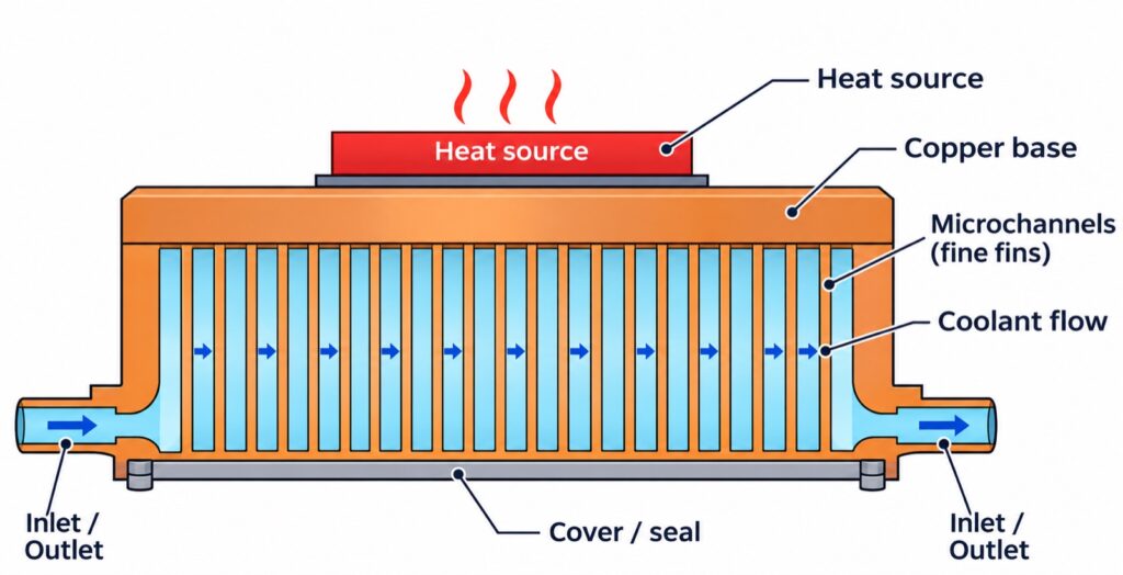
A microchannel heat sink is a liquid-cooled cold plate whose internal coolant passages are narrow — typically on the order of 0.1–1 mm in width and depth, with channel counts in the tens to hundreds across a single component. The concept was established in the 1980s at MIT Lincoln Laboratory (Tuckerman & Pease), whose microchannel heat sinks demonstrated that very small hydraulic diameters give a very large heat-transfer coefficient per unit volume — the reason a compact copper block can cool a high-flux device that a conventional fin stack cannot reach at the same size.
The physics that drives the design
Thermal performance is usually stated as thermal resistance Rth = ΔT / Q (K/W), the temperature rise of the heat source above the coolant per watt of heat removed. For a liquid cold plate, Rth is the sum of several resistances in series:
- Conduction through the copper base and channel walls (lower with thicker copper and shorter heat paths);
- Convection from the channel walls into the coolant — the dominant term, improved by smaller channels (higher area density and heat-transfer coefficient) but at the cost of higher pressure drop;
- Caloric rise of the coolant as it warms along the flow path (governed by mass flow × specific heat);
- Interface resistance between the device and the cold plate — normally managed with thermal interface material and flatness/contact pressure.
Narrower channels raise the convective coefficient and wetted area, so they lower Rth — but hydraulic resistance scales roughly with the inverse of channel size to a high power, so pressure drop rises steeply as channels shrink. Microchannel design is therefore a trade between thermal resistance and pumping power, not a simple “smaller is better”. This is the central engineering tension in a copper microchannel project.
Why copper
Copper is chosen for the base and walls because its thermal conductivity is roughly ~380–400 W/(m·K), several times that of aluminium, which lowers the conduction share of Rth and spreads heat laterally into the channel array. The trade-offs are higher density, higher material cost and machining behaviour that produces burrs and built-up edges more readily than aluminium.
Manufacturing challenges (and what “good” looks like)
Challenge 1 — Consistent fine-channel geometry
Channel width, depth, pitch and straightness must be held together. As channels narrow and multiply, tool rigidity, wear, vibration and chip evacuation become the limiting factors. A robust process fixes the critical dimensions and their inspectability first, then selects tooling, fixturing, machining sequence and inspection method: for example skiving or precision slot milling with a defined cutter path, stable workholding and in-process or post-process dimensional verification (optical or CMM with a fine probe).
Challenge 2 — Thin-wall (fin) stability
The copper ribs between channels are thin and sensitive to cutting force, clamping load and residual stress. Aggressive stock removal or poor fixturing causes uneven wall thickness, local bending or fin damage. Controlled depth-of-cut, balanced tool paths, adequate support and stress-relief sequencing keep the fins where the drawing puts them.
Challenge 3 — Burr control in copper
High-conductivity copper is prone to built-up edges, smearing and fine burrs, especially at channel entrances and fin tips. Burrs matter twice: they block coolant flow (raising pressure drop and creating hot spots) and they are hard to remove once a manifold is closed. A practical plan reserves an accessible deburring and cleaning route (mechanical, abrasive-flow or chemical) rather than assuming the as-machined edge is acceptable.
Challenge 4 — Joining and brazing the closed channel stack
When a design encloses the channels with a cover or a manifold, the joining process must not let filler enter the narrow passages while still sealing every edge. Joint clearance, filler quantity/placement, thermal profile and fixture alignment all matter; the thermal cycle can also distort the assembly. JYX CNC operates in-house brazing equipment and evaluates a suitable joining route against material and drawing requirements. Whether a specific photographed sample was brazed must come from process records, not from appearance.
Challenge 5 — Internal cleanliness
Narrow passages trap chips, burrs, cleaning residues and joining particles. Once closed, internal defects are hard to see, so cleaning is planned with the process sequence — flushing, cleanliness checks and flow-path/flow-rate verification selected to the geometry. A cold plate that is clean enough to assemble but blocked enough to run hot is a common and costly failure.
Challenge 6 — Sealing and functional verification
The part must meet both dimensional and operating requirements. Appearance cannot prove that passages are clear, joints are leak-tight, or pressure drop meets the design target. Verification is defined against customer requirements and can include critical-dimension inspection, leak testing, proof-pressure testing and, where specified, flow and pressure-drop measurement. No specific leak rate, pressure rating or thermal performance is claimed here without test data.
Numbers that matter (typical design envelopes, not product promises)
The table below summarises the parameter ranges that dominate a copper microchannel cold plate. They are industry design envelopes for orientation only; the actual values for any JYX part are fixed by the approved drawing and validated by inspection and test.
| Parameter | Typical range / note | Why it matters |
|---|---|---|
| Channel width / depth | ~0.1–1 mm | Sets heat-transfer area density and pressure drop |
| Fin (wall) thickness | Same order as channel width | Thin fins cool better but are harder to machine and keep straight |
| Copper conductivity | ~380–400 W/(m·K) | Lowers conduction share of thermal resistance |
| Copper melting point (C11000) | ~1083 °C | Sets the brazing temperature window vs the cover/base |
| Coolant pressure drop | Depends strongly on channel size, length, flow | The main trade against thermal performance |
| Leak test | Per customer spec (pressure/duration) | Sealing cannot be inferred from appearance |
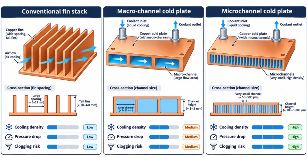
Note that “microchannel” is a relative term — there is no single fixed size boundary. Where measured dimensions do not support a fine-channel description, the part should be described as an internal-channel or milled-channel cold plate instead.
Microchannel vs macro-channel vs conventional fin stack
| Conventional fin stack | Macro-channel cold plate | Microchannel cold plate | |
|---|---|---|---|
| Heat-transfer area density | Low | Medium | High |
| Cooling per unit volume | Low | Medium | Highest |
| Pressure drop | Low | Low–medium | High (steep with narrower channels) |
| Clogging sensitivity | Low | Low | High — needs filtration & clean coolant |
| Manufacturing difficulty | Low | Medium | High (fine slots, thin fins, deburring, sealing) |
| Typical fit | Air-cooled electronics | Laser diode bars, IGBT, pumps | Very high-flux devices, dense power electronics |
Representative manufacturing route
(1) Drawing and thermal-requirement review; (2) material and blank preparation; (3) precision channel and interface machining (skiving/slot milling); (4) deburring and cleaning; (5) surface treatment, selective plating or brazing where required; (6) dimensional and functional inspection; (7) protective packaging. The exact sequence is set by material, geometry and customer acceptance criteria.
How it is verified
Verification is layered: dimensional inspection of channel width/depth/pitch, fin thickness and flatness; internal cleanliness and flow-path checks; leak and proof-pressure testing to the agreed method and limit; and, where the application requires it, flow-rate and pressure-drop (and thermal) testing under stated conditions. A pressure-hold test, a liquid leak test and a helium leak test are not equivalent — the correct method must be agreed with the customer.
Engineering trade-offs
More densely packed channels do not automatically give better system-level cooling: they also raise hydraulic resistance, pumping demand, contamination sensitivity and manufacturing cost. Manufacturability, verifiable cleanliness and assembly reliability must be evaluated together against the customer’s coolant, flow rate, operating pressure and heat load.
Frequently asked questions
How small can the channels in a copper cold plate be?
Designs commonly use channel widths and depths in the 0.1–1 mm range. The practical lower limit for a given part is set by machinability, achievable fin straightness, deburring and sealing, and the acceptable pressure drop — not by a single universal number.
Microchannel or macro-channel?
Choose microchannel when heat flux is very high and space is tight but the system can supply pressure and clean coolant. Choose macro-channel when lower pressure drop, tolerance to particles and easier cleaning/joining matter more than maximum heat-transfer density.
Can you guarantee a thermal resistance value?
Thermal resistance depends on the coolant, flow rate, heat load, interface and test setup. A figure is only meaningful with those conditions stated and measured; this article does not claim a guaranteed Rth for any part without test data.
How is leak-tightness proven?
By a defined leak or proof-pressure test to an agreed method, pressure and acceptance limit — not by visual inspection of the seam.
Discuss a copper liquid-cooling project
Developing a copper liquid-cooling heat sink, precision cold plate or complex internal-channel metal component? Send JYX CNC your 2D drawings, 3D models, material requirements, expected quantities and critical operating conditions for a manufacturability review and quotation.
Review the copper microchannel heat sink and joining capability against the project requirements. Request a drawing review for your copper liquid-cooling component.
Sources
- Copper Development Association, Copper for Busbars and Architectural Applications (thermal/expansion reference data). copper.org
- Tuckerman & Pease, microchannel heat-sink work, MIT Lincoln Laboratory (historical basis of microchannel liquid cooling). MIT LL
- Reference melting point & hardness data for C11000 copper and common alloys. reference table
Figures above are cited for engineering orientation. Product-specific dimensions, materials, joining methods and test results are governed by the approved drawing and verification records.