
On this page
Engineering summary. A robot joint housing is not judged on its outside shape — it is judged on the relationship between its features. Two bearing bores that are not coaxial, or an end face that runs out from its bore, make a joint that binds, wears its bearing and loses repeatability, no matter how good the machining looks. The housing also has to be light, which means thin walls and weight pockets right next to the precision bore — the two requirements pull against each other. Here is how to balance those requirements when designing a robot joint housing blank.
What decides a joint is the relationship, not the geometry
Most of a robot joint housing is simple — a pocketed block with holes. The part that decides whether the robot works is small: the coaxiality of the two bearing bores and the run-out of the end face that seats the bearing. If the bores are off-axis, the shaft sits at an angle; if the end face runs out from its bore, the bearing races tilt and preload goes uneven. Both show up as a joint that is stiff in one position and loose in another, or that heats up and wears early. So the drawing should spend its tight tolerances on those relationships — coaxiality and face run-out — and leave the rest of the geometry at a general tolerance, instead of chasing ±0.01 mm on every outside face that nothing measures off.
Bore accuracy is made in steps, in one setup
A bearing bore that holds its diameter, roundness and position is not cut in one pass. The reliable route is rough boring to remove most material and let the part move, semi-finishing, then finish boring or reaming to final size and roundness and surface finish. The face that seats the bearing is machined in the same setup as the bore, so its run-out and perpendicularity to that bore come from the machine, not from a second fixturing that adds error. If a shop finishes the bore in one setup and the face in another, the tolerance between them is the sum of two setups — and that is where a joint loses its accuracy. Ask for the bore and its seating face to be machined together. Industry practice for robot joint bearing bores commonly states coaxiality and face run-out around ±0.005 mm; treat that as the target to specify, and confirm it is measured on your part, not just claimed.
Lightweighting fights the bore — design the wall, not just the pocket
The reason a robot joint is machined from aluminium with deep weight pockets is mass: every gram at the end of an arm costs torque and speed. But the pocket walls that save that mass sit right next to the bore that must stay round. A thin wall under the bearing bore deflects when the bearing is pressed in and when the joint is loaded, and a bore that was round in the free state goes oval under preload. The fix is to keep enough material and stiffness around the bore and its seat — a boss around the bore, ribs to the pocket walls, a floor thick enough not to dish — and to pocket elsewhere. Cutting the pocket as thin as possible everywhere is how you get a light part that will not hold a bearing. Stiffness near the bore and lightness away from it can coexist; it is a design decision, not a machining one.
Thin walls and residual stress: it moves after the machine
A pocketed aluminium housing is exactly the shape that moves after machining. Removing the pocket releases stress from the billet, and the thin walls around it spring; a part that measured true at inspection can be slightly out in a week. For a joint housing, that means: ask for a stress-relief step in the process, finish the critical bore and face after the pocket has been roughed (rough, stress-relieve, then finish), and measure the critical relationships after the part has settled. Roughing everything, then finishing everything in one go, leaves the finish cut fighting the stress the rough cut released.
The anodise can tighten the bearing bore
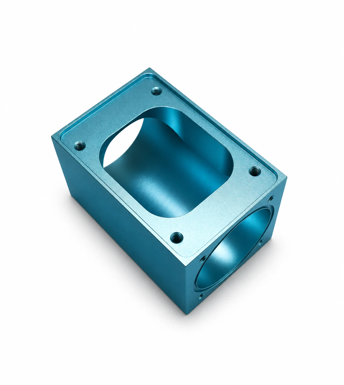
Robot joint housings are usually anodised, and anodising grows the surface — into the aluminium and out of it. A bore that was to size before anodising can be undersize after, and a bearing that pressed in freely on the bench will not go in after coating. Mask the bearing bore and its seating face so they stay bare and machined, or machine the bore larger before anodising to allow for coating growth into the bore. Either way, the drawing has to say which faces hold their machined dimension after anodising and which get coated — a general “anodise the part” leaves the bore to chance.
What we make, and what we do not
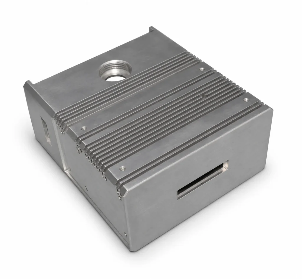
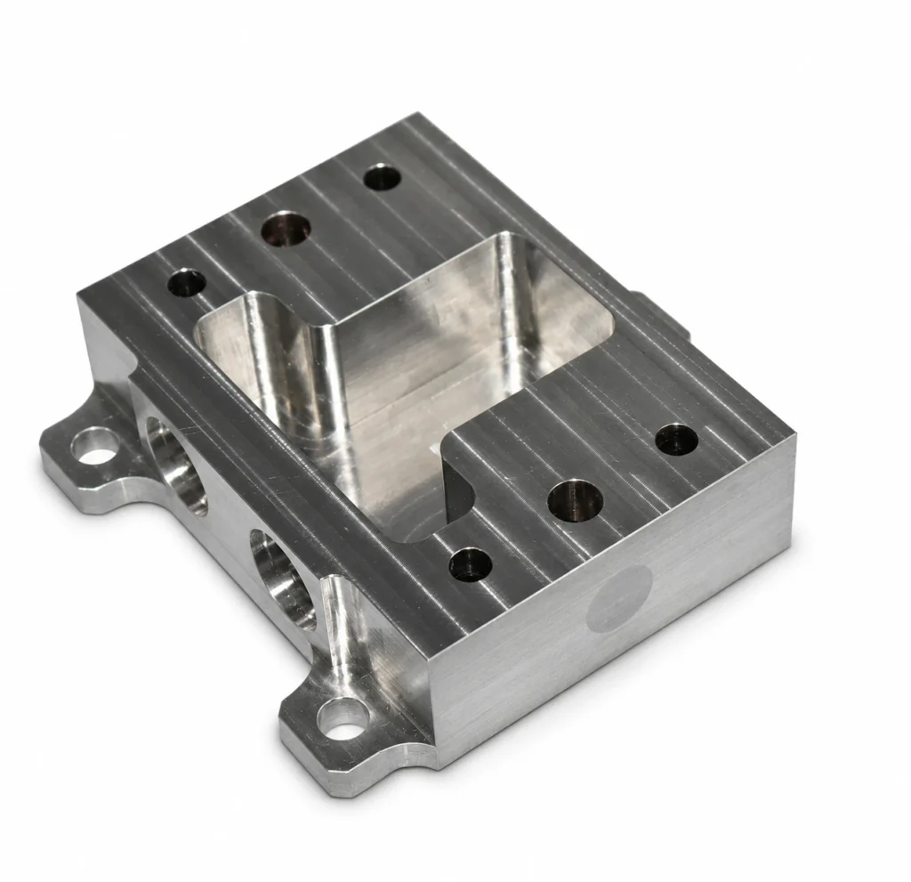
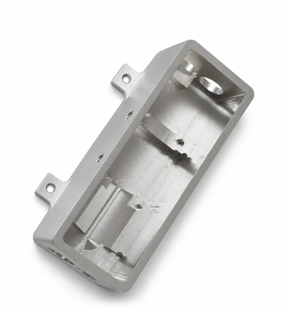
We machine robot joint housings and motion parts from aluminium, stainless and titanium — pocketed housings, bearing bores, coaxial bolt patterns, machined end faces — to drawing, with the bore, its seating face and the bolt pattern made and inspected as specified, and we can hold coaxiality and face run-out to a stated tolerance and measure it.
We do not promise a tight coaxiality on a wall that is too thin to hold it, and we will say so before cutting rather than after. We will tell you when a weight pocket has taken stiffness away from the bore, when the anodise will move a bearing fit, or when the drawing puts its tolerance on the wrong feature — those are cheap on the drawing and expensive on a joint that will not repeat.
What to send with the RFQ
Send the drawing revision, 2D drawing and STEP model; the alloy; which bores and faces carry the bearing and must hold coaxiality and run-out, and to what tolerance; the bearing fit and preload; the weight and stiffness targets; which faces are masked versus anodised; the load the joint carries; and the inspection and acceptance criteria (including how coaxiality and run-out are measured). With those we can quote a housing that holds the joint, not one that merely looks machined.
Request a quote for robot joint housing machining.
Frequently asked questions
Why does my joint bind in one position and not another? Usually coaxiality or face run-out, not the bore diameter. If the two bores are slightly off-axis or the seating face runs out, the bearing tilts and preload rises on one side. Tighten the relationship tolerances (coaxiality, run-out), not the diameter alone.
Can you make it light without losing bearing accuracy? Yes, if stiffness is kept where the bore is and material is removed away from it — a boss and ribs around the bore, pockets elsewhere. A uniformly thin pocketed wall holds weight well and bearings badly. Light and accurate is a design choice, not a contradiction.
Why did the bearing not fit after anodising? Anodising grows into the bore and shrinks it. Mask the bearing bore and seat, or machine it larger before anodising based on the expected coating growth. It has to be stated on the drawing which faces stay bare after coating.