
On this page
Engineering summary. Machining an aluminium housing is three problems that fight each other: thin walls that deflect while you cut them, tolerances that have to be met on a part that is not rigid, and a final anodise that changes the very dimensions you just held. Get any one wrong and the housing does not fit. This page is about making the three agree — where the wall is too thin, which dimensions the anodise will move, and how to put the finished condition on the drawing instead of the bare-metal one.
Thin walls are the first thing that goes wrong
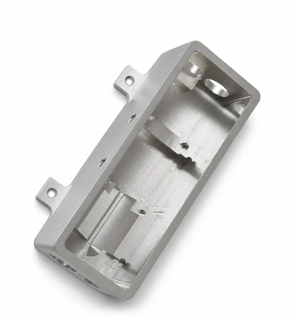
Aluminium cuts easily, which tempts you to leave walls thin to save weight — and thin walls are where a housing fails. A tall thin wall deflects away from the tool as it is cut and springs back after, leaving chatter marks and taking the dimension off. The predictor is not wall thickness alone but the aspect ratio, wall height divided by thickness: a tall thin wall at a high ratio will move, a short thick wall at the same thickness will not. If the design needs a thin wall, it needs a rib or a boss to stiffen it, or the wall has to come down in height. Machining a wall that the geometry cannot hold is how you get a scrapped casting.
Clamping and residual stress: it moves after it leaves the machine
Two distortions hit aluminium housings and neither shows on the drawing. Clamping: a thin wall held too hard is pressed out of shape while cut, then springs back on release, so the machined face is no longer where the tool left it. Residual stress: removing material from plate or extrusion releases locked-in stress, and the part can move hours or days later — flat at inspection, bowed in assembly. For a housing with a critical face, ask for a stress-relief step and flatness measured after the part has settled, not straight off the machine. Soft jaws and a support under thin floors are not optional on a thin part; they are what keeps it in tolerance.
Anodising grows the surface — and moves your fits
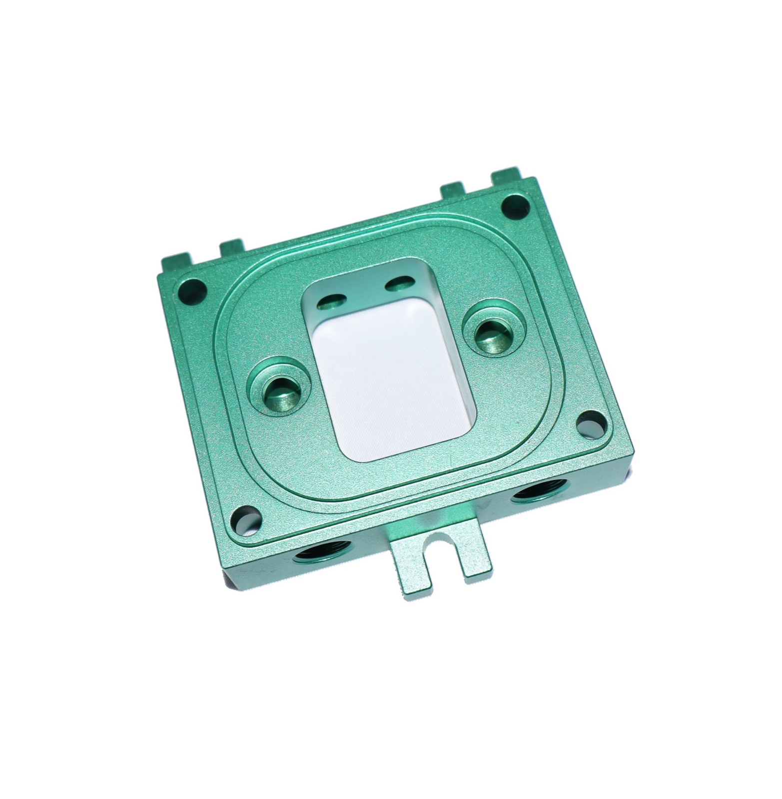
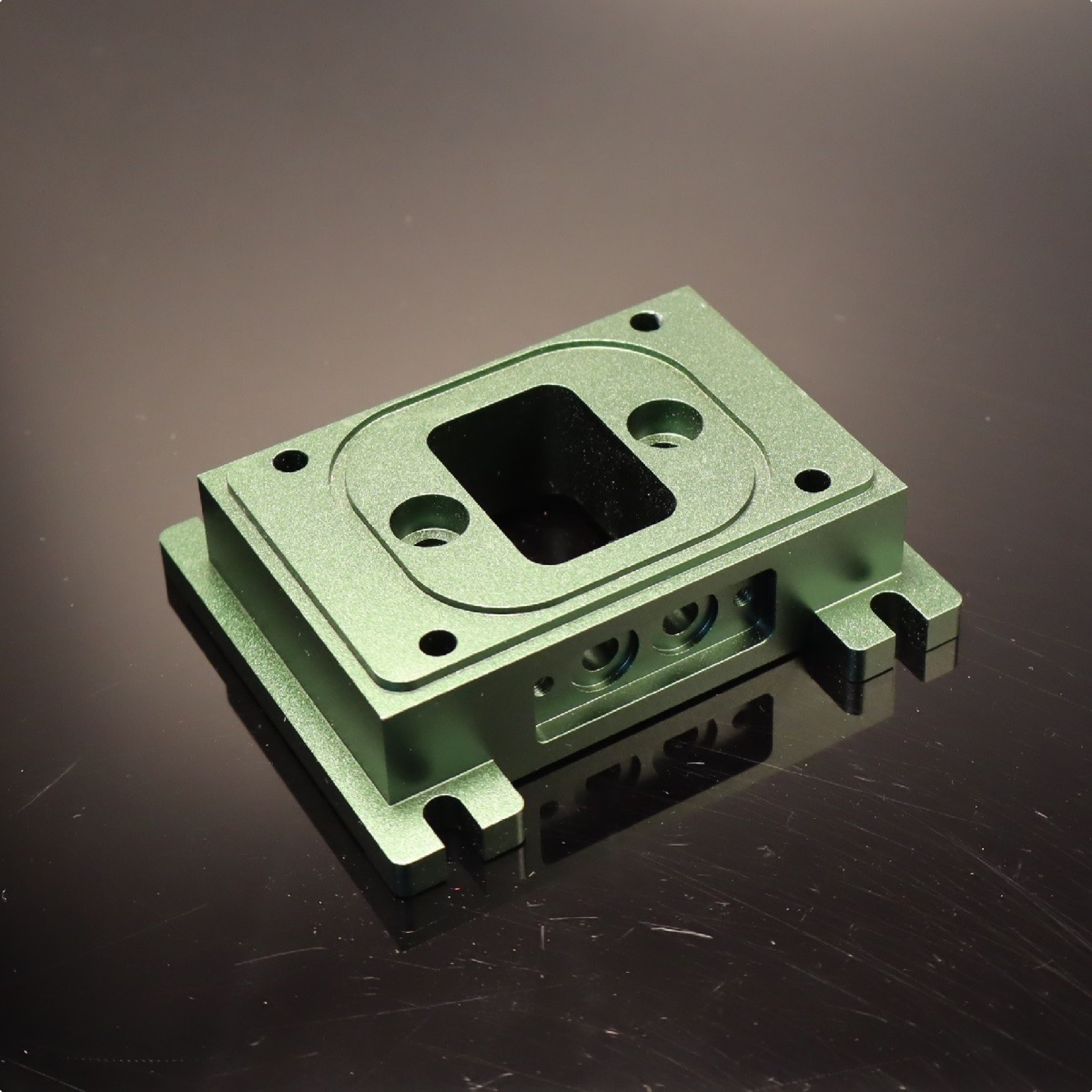
This is the trap most drawings miss. Anodising is not a coating laid on top; it is an oxide that grows partly into the aluminium and partly out of it. For conventional Type II, roughly two-thirds grows inward and one-third outward. A 15 µm Type II layer on a shaft grows about 5 µm per side outward, so the diameter grows by about 10 µm; the same layer in a bore reduces the bore by about 10 µm. So an external diameter comes out slightly larger, a bore slightly smaller, and a thread or a bearing fit can go out of tolerance. If a bore, a shaft, a thread or a locating face controls assembly, the drawing has to state the finished, post-anodise dimension, and the shop has to machine the bare metal undersize or oversize to hit it — or mask that face so it does not get anodised at all.
State the finished condition, not the bare-metal one
The single most useful thing on an aluminium housing drawing is clarity about which dimensions are bare-metal and which are finished-after-anodising. Mark the faces that must hold tolerance after coating; mark the faces to be masked; give the anodise type and thickness; and say how the finished dimension is checked. A drawing that says “anodise” and leaves every dimension bare-metal produces a part that was right before coating and wrong after. The finishing spec and the dimensional spec are one specification, not two.
Threads, bores and mating faces need a decision each
- Threads: an anodised thread gets tighter; fine threads and small pitches can stop accepting a mating part. Mask the threads, or cut them for the post-coating fit — decide on the drawing.
- Bores and bearing fits: bore shrinks by twice the per-side growth; design the allowance in, or mask and ream after.
- Sealing or mating faces: a face that must seal flat should usually be masked — an anodic layer is hard and can be uneven at an edge, and a masked machined face seals better than a coated one.
- Cosmetic faces: these can be anodised freely; that is where the colour and the wear layer belong.
Material choice is part of the machining plan
6061 machines cleanly and anodises to a good finish; 7075 is stronger but its anodise and its machinability behave differently. The alloy and temper decide how much the part moves, how thin a wall will hold, and how the finish looks — so it belongs in the same conversation as the tolerances, not a separate one after. (See our 6061 vs 7075 guide for the selection side.)
What we make, and what we do not
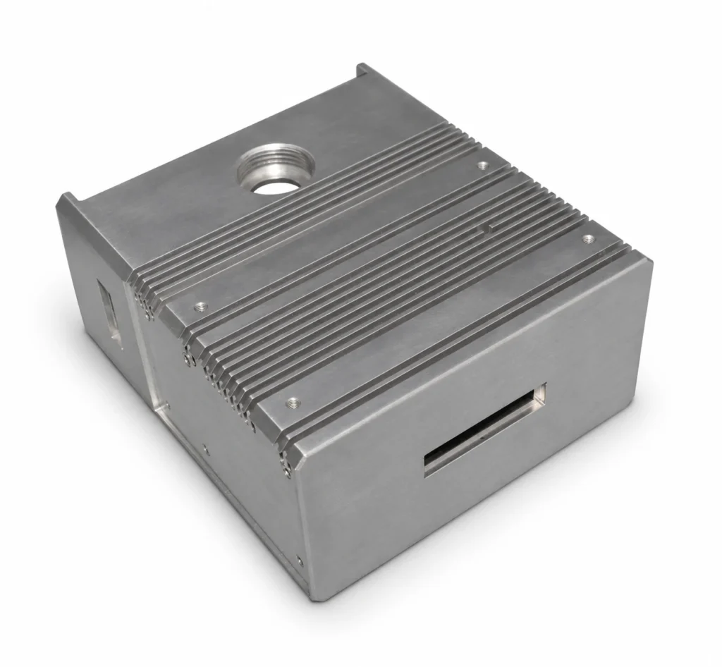
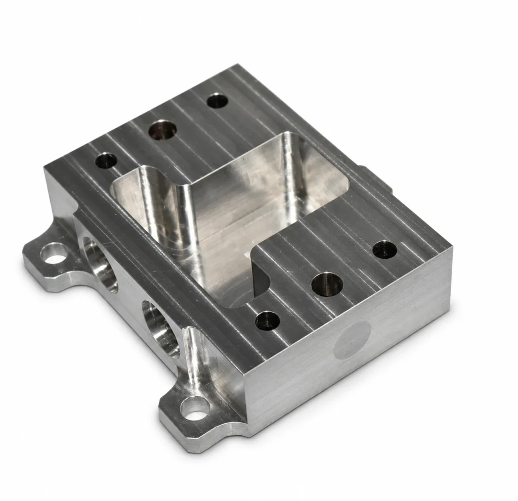
We CNC-machine aluminium housings — milled pockets, walls, bores, threads and mounting faces — from plate or extrusion, in 6061, 7075 and other grades, and we machine to the finished condition you specify, including allowances for anodising and masked faces. We inspect critical faces and bores as agreed.
We do not promise a bare-metal dimension will still hold after anodising if the drawing did not allow for the growth, and we will say so before cutting rather than after. We will tell you when a wall is too thin for its height, when a bore needs an allowance, or when a thread should be masked — those are cheap to fix on the drawing.
What to send with the RFQ
Send the drawing revision, 2D drawing and STEP model; the alloy and temper; the wall thicknesses and any thin features; which dimensions must hold after anodising and which are bare-metal; the anodise type (II or III), thickness and colour; which faces are masked versus anodised; the thread and bore fits that control assembly; and the inspection and acceptance criteria. With those we can quote a housing that fits after finishing, not one that only fits before.
Frequently asked questions
My bore measured right before anodising but the part will not fit after. Why? Anodising grows inward and outward; a bore shrinks by about twice the per-side growth — roughly 10 µm on a 15 µm Type II layer. The bore has to be machined oversize by that amount, or masked and reamed after coating. It is a drawing decision, not a machining error.
How thin can an aluminium wall be? There is no single number — it is the aspect ratio (height over thickness) that decides whether it holds. A short thick wall can be thinner than a tall one at the same thickness. If the height forces a thin wall, add a rib or lower the wall; do not expect the machine to hold a wall the geometry makes flexible.
Should I mask the sealing face before anodising? Usually yes. An anodic layer is hard and can be uneven at an edge; a masked machined face seals flatter and holds its dimension. Mark it on the drawing — a general “anodise the part” instruction does not tell the shop which face must stay bare.