
On this page
Engineering summary. A liquid cold plate has two faces that do different jobs, and most leak problems come from treating them as one. The face against the chip must conduct heat; the face where the coolant is sealed must stay closed under pressure and temperature cycles. Flatness on the drawing means nothing until you say which face — and in which state, bolted or free. This page is about the sealing face specifically: O-ring grooves, flange stiffness, weld versus elastomer seals, and how to test what you actually built.
For the complete cooling specification, use the AI server cold-plate RFQ guide. Compare the aluminum liquid cold plate and joining capability with your chosen seal design.
The two faces of a cold plate are not the same problem
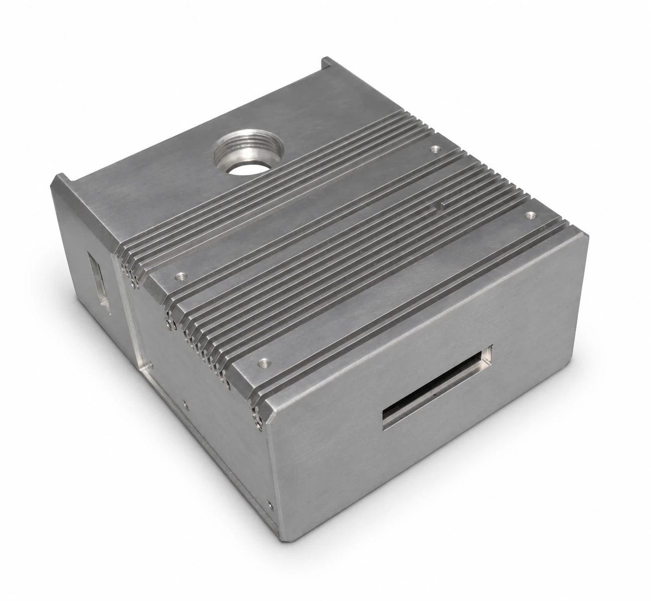
The top face of a cold plate presses against a chip or a TIM pad; its job is to pass heat across a thin interface. The face where coolant enters and where the lid or manifold joins is a sealing face; its job is to keep fluid in at pressure, through thermal cycling, for years. They are measured differently, specified differently, and failed by different causes. A plate can have excellent die-side flatness and still weep at the port groove, because the groove depth, the flange stiffness or the bolt pattern was wrong — none of which the die-side number captures.
When a drawing says only “flatness 0.05 mm,” ask which face and which state. On a thin lid over a wide channel, free-state and bolted-down flatness can differ by more than the tolerance itself.
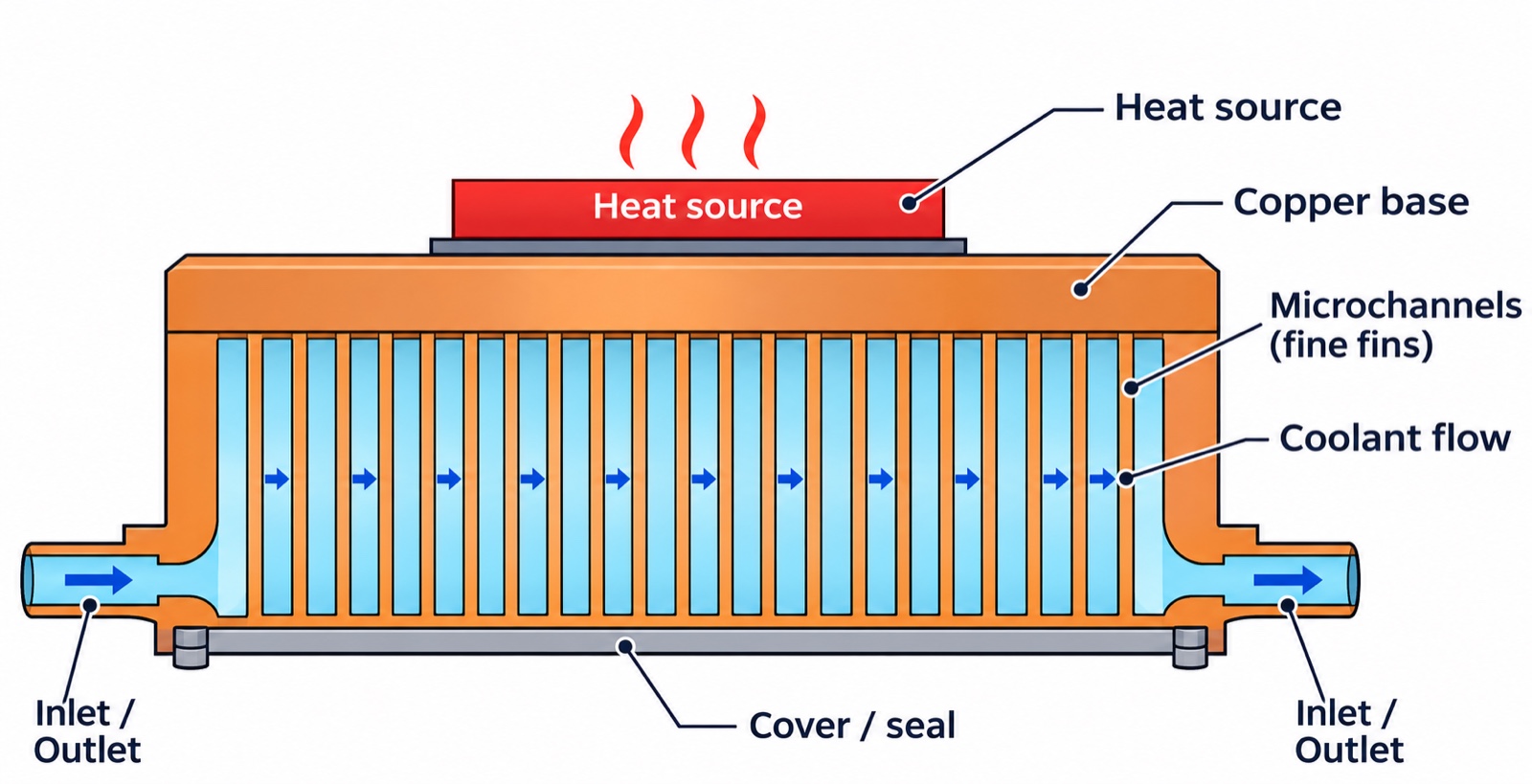
Flatness has a state — sealing faces fail in the clamped state
The number that leaks is the one measured with the part bolted to its mating face at the real torque, not the number off the surface table. Machining releases residual stress; clamping puts it back. A wide, thin lid between two bolt rows bows between the bolts. So the sealing face has to be specified in its assembled state, under a stated clamp load, with a stated bolt pattern — and that means the shop needs a fixture to verify it, not just a granite plate.
Industry practice for machined cold plates commonly lands in the range of about 0.02–0.05 mm flatness over a 300 mm span, measured as the drawing requires. That is a reference point quoted by machining shops, not a guaranteed value for any specific plate — a wide thin lid and a small thick block do not share a number, and the required value depends on the seal type, the pressure and the mating stiffness.
O-ring grooves: depth, width and the corner nobody checks
For an elastomer seal, the groove — not the flat face — is the controlling feature. Three dimensions decide whether the O-ring seals: the groove depth (sets the squeeze), the groove width (sets the fill and room to roll), and the surface finish of the groove floor and walls (a rough floor gives the O-ring a leak path under it). Typical shop targets reported for cold-plate sealing grooves are around ±0.02 mm on depth and a floor finish of roughly Ra 1.6 µm or better; hard seals and high pressure want tighter. Treat these as common industry figures and confirm against your seal vendor’s squeeze recommendation, because the O-ring datasheet, not the drawing template, sets the real target.
Two shop-floor details decide yield here: cut the groove before deburring the edges, so a deburr tool does not roll a burr into the sealing path; and check the groove for a continuous floor — an interrupted cut from a worn insert leaves a step the O-ring cannot bridge.
Bolts, flanges and why the seal opens in the middle
A sealing face held by bolts is a clamped beam between supports. The bolts pull the edges down; the middle lifts unless the flange is stiff enough or the bolt spacing is close enough. This is why a plate that holds pressure on the bench can weep after it is mounted to a manifold that pulls it into a different shape. Two practical rules: keep bolt spacing tight relative to the flange width, and specify the mating face’s flatness too — a flat lid on a dished manifold still opens a gap.
Weld or elastomer: two different seals, two different failure modes
- Brazed or welded seal (friction stir, brazed, diffusion-bonded): no O-ring to replace, but the joint quality is invisible from outside. It is proven by leak test and by sectioning a coupon, not by appearance. A joint that passes a pressure-hold can still fail a tracer-gas test at a pinhole.
- Elastomer seal (O-ring or gasket): serviceable and tolerant of minor mismatch, but it relies on squeeze that relaxes over time and temperature. It fails by compression set and by groove damage, not by cracking.
Mixing the two on one part — a welded body with an O-ring port — is common and fine, but each interface has to be specified and tested on its own terms. Do not assume one leak test at the port proves the body weld.
How to test what you actually built
Pressure-hold and tracer-gas are not the same test, and passing one does not imply the other. A pressure-hold test at the working pressure proves the part holds static pressure for the hold time; it can miss a micro-leak that only shows at temperature or under a tracer gas. A helium (tracer-gas) test finds smaller leaks but only where the probe reaches. State which test, at what pressure, at what temperature, with what acceptance rate and what instrument — “leak tested” alone is a label, not a specification. For high-reliability plates the realistic order is: proof pressure, then tracer-gas on the sealed joints, then a thermal cycle and re-test, because the cycle is what opens a marginal seal.
Surface finish and coating on the sealing face
A sealing face is not a place to hide a finish problem. Anodising and plating build a layer that changes groove depth and floor finish; a thick or uneven coating on a sealing groove can turn a good groove into a leaker, and a masked zone that should have been coated can corrode. If the part is anodised or plated, say so on the drawing alongside the groove dimensions, so the groove is cut to the finished, coated state and not the bare-metal state.
What we make, and what we do not
We machine aluminium and copper cold plates, cut coolant channels, cut sealing grooves and port threads, and inspect to drawing. Where the design calls for a joined body we machine and prepare the joint and can carry out joining processes per the approved design; the joint is proven by the agreed leak test, not by appearance.
We do not publish a flatness, groove tolerance or leak rate as a house standard, because the right value depends on your seal, pressure, flange and mating part. We do not claim a hermeticity class beyond what is tested and agreed on the drawing. Bring the seal type and the operating conditions and we will specify a manufacturable groove and a test that matches it.
What to send with the RFQ
Send the drawing revision, 2D drawing and STEP model; which face is the sealing face and which is the thermal contact face; the seal type (O-ring durometer and cross-section, gasket, or welded body) and the groove dimensions you intend; the flatness requirement with its state (free or assembled), clamp load and bolt pattern; the working and proof pressure and temperature range; the leak-test method and acceptance criterion; and any anodising or plating and its thickness on the sealing zones. With those we quote a seal that can be tested, not just a plate that can be machined.
Send the cold-plate drawing, seal type and acceptance criteria for review
Frequently asked questions
Can a cold plate be flat enough for the chip and still leak? Yes. Die-side flatness and sealing-face integrity are different requirements met by different features. A plate can pass the thermal-face check and still weep at a groove that is too shallow or a flange that bows between bolts.
Is “flatness 0.05 mm” enough to specify the seal? Not by itself. It needs the face, the measured state (free or clamped), the clamp load and the bolt pattern. Without those, two suppliers will build two different parts and both will claim they met the number.
Does a pressure-hold test prove the seal? It proves the part holds static pressure for the hold time. It does not prove there is no micro-leak that a tracer-gas test or a thermal cycle would expose. Specify the test that matches the reliability you need.