
On this page
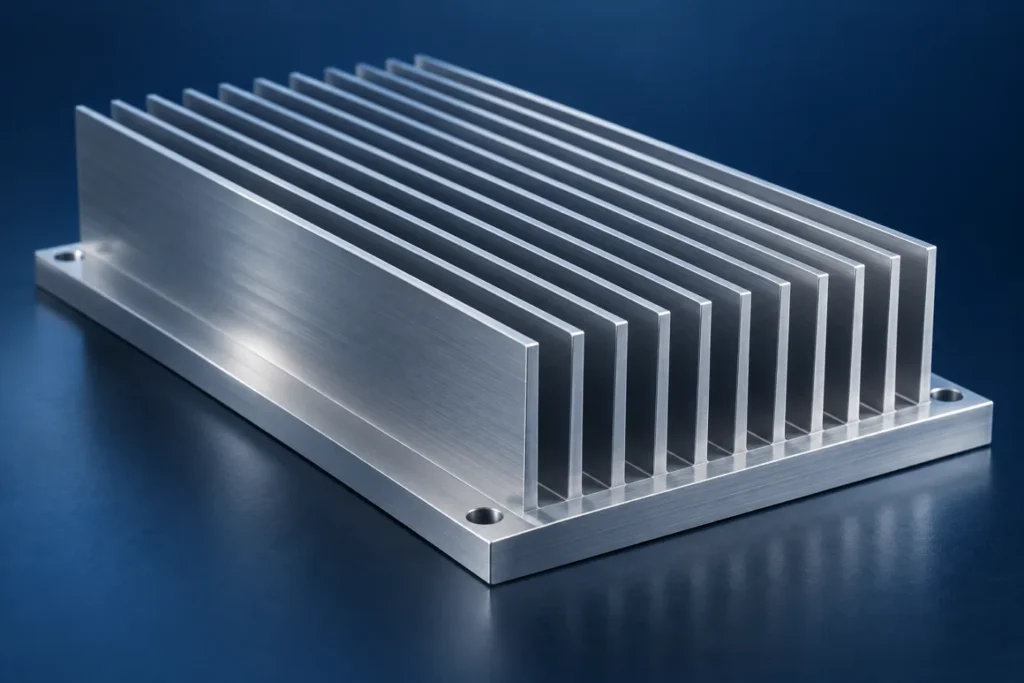
Engineering summary. A precision finned heat sink must match heat load and airflow, preserve the mounting interface and be tested under defined boundary conditions. Fin spacing, base geometry, manufacturing and inspection work together.
| Design element | Define before quotation | Check or validate |
|---|---|---|
| Fin geometry | Spacing, height, orientation and envelope | Tool access, fin integrity and airflow |
| Mounting base | Datums, interface flatness and mounting method | Measurement at the agreed stage |
| Thermal test | Heat load, air temperature, airflow and sensors | Record boundary conditions and method |
Introduction
Finned heat sinks remain an important thermal-management option for semiconductor lasers and optoelectronic equipment, particularly where the heat load and available airflow allow passive or forced-air cooling. Their performance depends on fin area, spacing, height, orientation, base thickness and the contact between the heat sink and the device. The 2021 review by Yan and colleagues notes that conventional finned heat sinks are relatively straightforward to manufacture and assemble, but that their cooling capacity can become insufficient as laser power and packaging density increase. This makes geometry optimization and clear performance limits essential.
1. Fin geometry must fit the actual cooling condition
Increasing fin area can improve heat transfer, but simply making fins thinner or closer together is not always beneficial. If the spacing is too small for the available airflow, the pressure drop may increase and the air may not effectively reach the full fin surface. Fin orientation and installation angle can also change the airflow pattern and heat-transfer behaviour.
For a custom heat sink, the key design inputs include the device’s heat load, the airflow direction and speed, the ambient temperature, the allowed component temperature and the available envelope. A design intended for natural convection may need a different fin spacing and orientation from one used with a fan or ducted airflow. Simulation can help compare options, but prototype testing is needed to validate the final assembly and boundary conditions.
2. Material choice and the role of the base
Aluminium is widely used for finned heat sinks because it combines useful thermal conductivity with low weight and good machinability. Copper may be considered where thermal conductivity is a priority and additional mass or cost is acceptable. For laser packages requiring controlled thermal expansion or a more specialized thermal path, materials such as MoCu or CuW may be considered for heat spreaders or submount-related components rather than automatically replacing aluminium throughout the assembly.
The base thickness and flatness influence heat spreading and the contact to the laser module. If the base is too thin, machining or assembly loads may distort it; if it is unnecessarily thick, the design may add weight and cost. Material and geometry should therefore be selected together, with critical dimensions tied to the actual mounting and cooling requirements.
3. CNC manufacturing of fins and mounting features
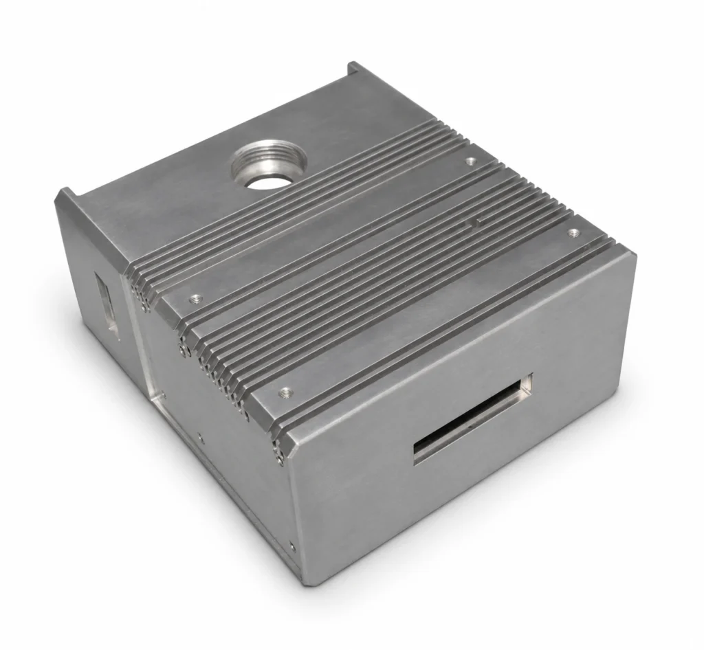
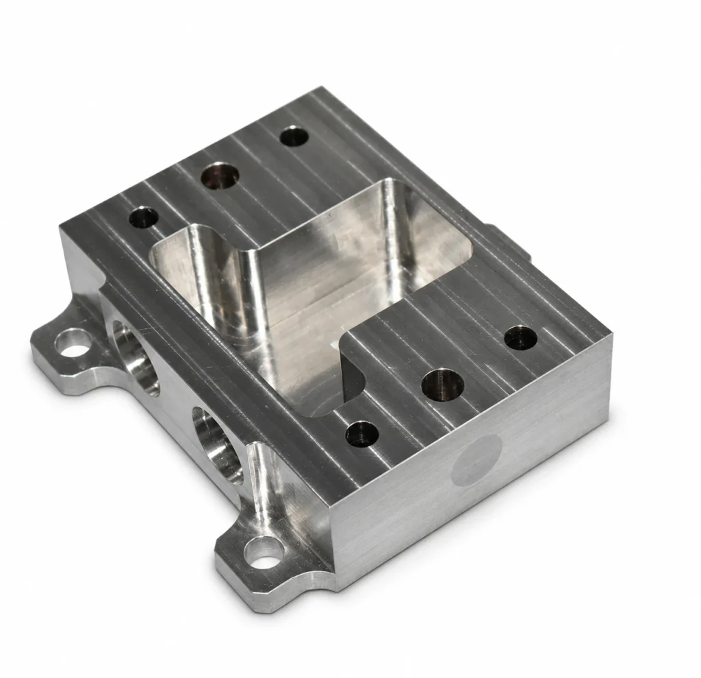
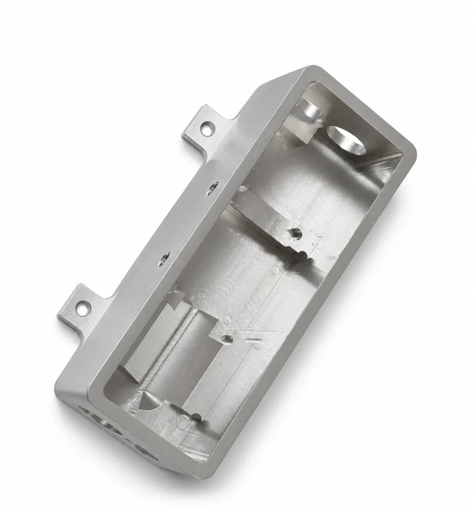
Depending on the part geometry, precision heat sinks may be manufactured by CNC milling, profile machining, drilling, pocketing and finishing operations. Dense fin structures require careful control of tool diameter, tool reach, chip evacuation and cutting forces. Thin fins can be damaged by handling or deburring, while a large base may distort if the machining sequence or workholding is unsuitable.
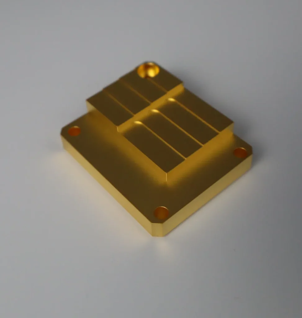
A practical process plan can include rough machining, stress- or distortion-aware intermediate checks where necessary, finish machining of critical mounting surfaces, controlled deburring and cleaning. The drawing should clearly identify the mounting datum, critical flatness or parallelism requirements, hole positions and any surfaces that must remain free of coating. For complex parts, a 3D model can help evaluate tool access and identify features that are difficult to inspect after machining.
4. Surface treatment and assembly interfaces
Some heat sinks require anodizing, conversion coating or another surface treatment for corrosion protection, electrical isolation or appearance. Surface treatment can alter dimensions and contact behaviour, so the drawing should identify which areas may be treated and which interfaces must remain conductive or in direct thermal contact. The chosen finish must be compatible with the base material, operating environment, fasteners and any thermal-interface material.
Assembly quality also depends on the contact between the heat sink and the laser package. Burrs, local high points, contamination, uneven fastener loading or an unsuitable thermal-interface layer can increase thermal resistance. For this reason, a good manufacturing specification treats the contact surface as a functional interface rather than a cosmetic face.
5. Inspection methods and thermal tests
For a precision heat sink, inspection should link dimensional requirements to thermal function. Typical methods may include:
- CMM or suitable dimensional measurement for mounting holes, datums and overall geometry.
- Flatness and parallelism measurement on the base and mating faces.
- Fin-spacing, fin-thickness and fin-height checks using suitable gauges or optical measurement.
- Surface-roughness measurement where specified.
- Visual inspection for fin damage, burrs, tool marks and contamination.
- Coating-thickness or coating-quality checks where a surface treatment is specified.
- Thermal testing under defined heat load, airflow, ambient temperature and mounting conditions.
Thermal testing should record the test setup and boundary conditions. A temperature result without the applied heat load, airflow and sensor positions may not be comparable with another design. For higher-power laser assemblies, the customer may also require temperature mapping or thermal-resistance evaluation of the complete device-to-heat-sink interface.
6. From prototype to repeatable production
A heat sink that performs well as a one-off prototype may still be difficult to manufacture consistently at scale. Repeatability depends on stable material supply, tool life, workholding, machining sequence, deburring, surface treatment and inspection. Design-for-manufacturing review can identify opportunities to simplify fin geometry, standardize tooling, improve inspection access and reduce unnecessary tight tolerances.
Jingyixin’s relevant product scope includes custom precision aluminium heat sinks, thermal-management components and precision CNC parts. Projects can be reviewed from 2D drawings, 3D models or physical samples, with manufacturability assessed against the required geometry, material, surface finish, quantity and inspection criteria. The final thermal performance should be confirmed through application-relevant testing rather than assumed from the part geometry alone.
Conclusion
A precision heat sink is successful when its thermal design can be manufactured repeatedly and verified under realistic operating conditions. Fin geometry, base flatness, material selection, surface treatment and mounting interfaces should be treated as one integrated design problem. Combining design-for-manufacturing review with dimensional inspection and thermal validation helps bridge the gap between a CAD model and a dependable production component.
Technical Note
This article draws on published research and general engineering principles to provide insights into precision manufacturing and thermal management. Actual material specifications, manufacturing processes, tolerances, performance requirements, and inspection criteria are evaluated on a project-by-project basis in accordance with approved engineering drawings and customer specifications. All product capabilities and performance claims are subject to verification for the specific application.
Frequently asked engineering questions
Does closer fin spacing always improve cooling?
No. The best spacing depends on airflow, fin geometry and mounting conditions; restrictions in the airflow path can reduce useful heat transfer.
Does base flatness alone prove thermal performance?
No. Flatness is one interface requirement. Thermal testing should also state the heat load, airflow, ambient temperature, mounting and sensor locations.
What should a heat-sink quotation request include?
Provide drawings, material, fin dimensions, mounting datums, surface treatment, quantities and acceptance criteria. Include heat load and airflow conditions when a thermal test is required.
Technical references
Yan et al., Review of Issues and Solutions in High-Power Semiconductor Laser Packaging Technology, Frontiers in Physics (2021). See also Alpha: heat sinks for natural convection.
Related engineering resources
- Laser package thermal path
- Liquid-cooled cold plate design
- Aluminum liquid cold plate
- Copper heat sink
- Precision CNC machining
- Single-Crystal Diamond Heat Spreaders: Materials, Interfaces and Design
- Diamond Thermal Components: Manufacturing Requirements and Inspection
Discuss drawings and requirements with JYX engineering; project scope and capabilities are confirmed before quotation.